
Method for uplink spectrum monitoring for sparse overlay TDMA systems

a sparse overlay and spectrum monitoring technology, applied in the field of wireless communication, can solve the problem of at least confronting the prior ar

Inactive Publication Date: 2004-09-14
AMERICAN TELEPHONE & TELEGRAPH CO
View PDF5 Cites 37 Cited by
  • Summary
  • Abstract
  • Description
  • Claims
  • Application Information

AI Technical Summary

Benefits of technology

"The invention is about a microcell base station controlling a wireless mobile device in a mobile communication network. The base station transmits control signals to the mobile device to set various parameters such as the access parameter, the delay parameter, and the scan timer. By doing so, the base station can prevent the mobile device from leaving the current control channel and can force the mobile device to measure the signal strength of other control channels. The mobile device then takes appropriate action based on the measured signal strength. The technical effect of the invention is to enhance the ability of the base station to control the mobile device and improve the reliability of the mobile communication network."

Problems solved by technology

However, in sparse systems where there are relatively few microcell base stations 10 in a region, it is not desirable to cause a registered mobile station 20 to undertake control channel reselection.
Thus, the prior art is confronted with at least two problems.
The second problem is to reduce the probability that a call initiated by a mobile during an uplink spectrum-monitoring measurement by a microcell base station, will cause the transfer of the call to a macrocell base station.

Method used


Image

  • Method for uplink spectrum monitoring for sparse overlay TDMA systems
  • Method for uplink spectrum monitoring for sparse overlay TDMA systems
  • Method for uplink spectrum monitoring for sparse overlay TDMA systems

Examples


Embodiment Construction

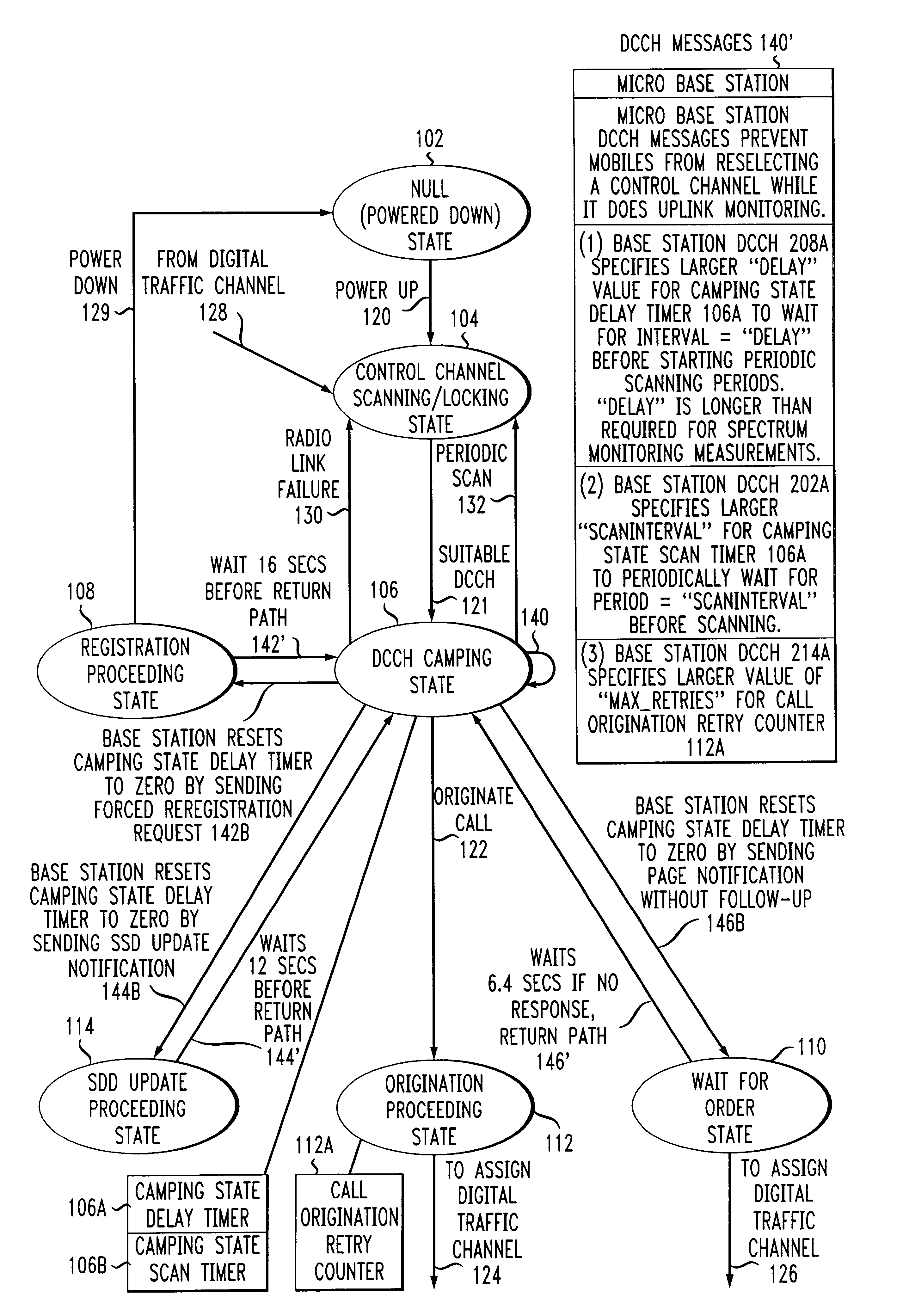
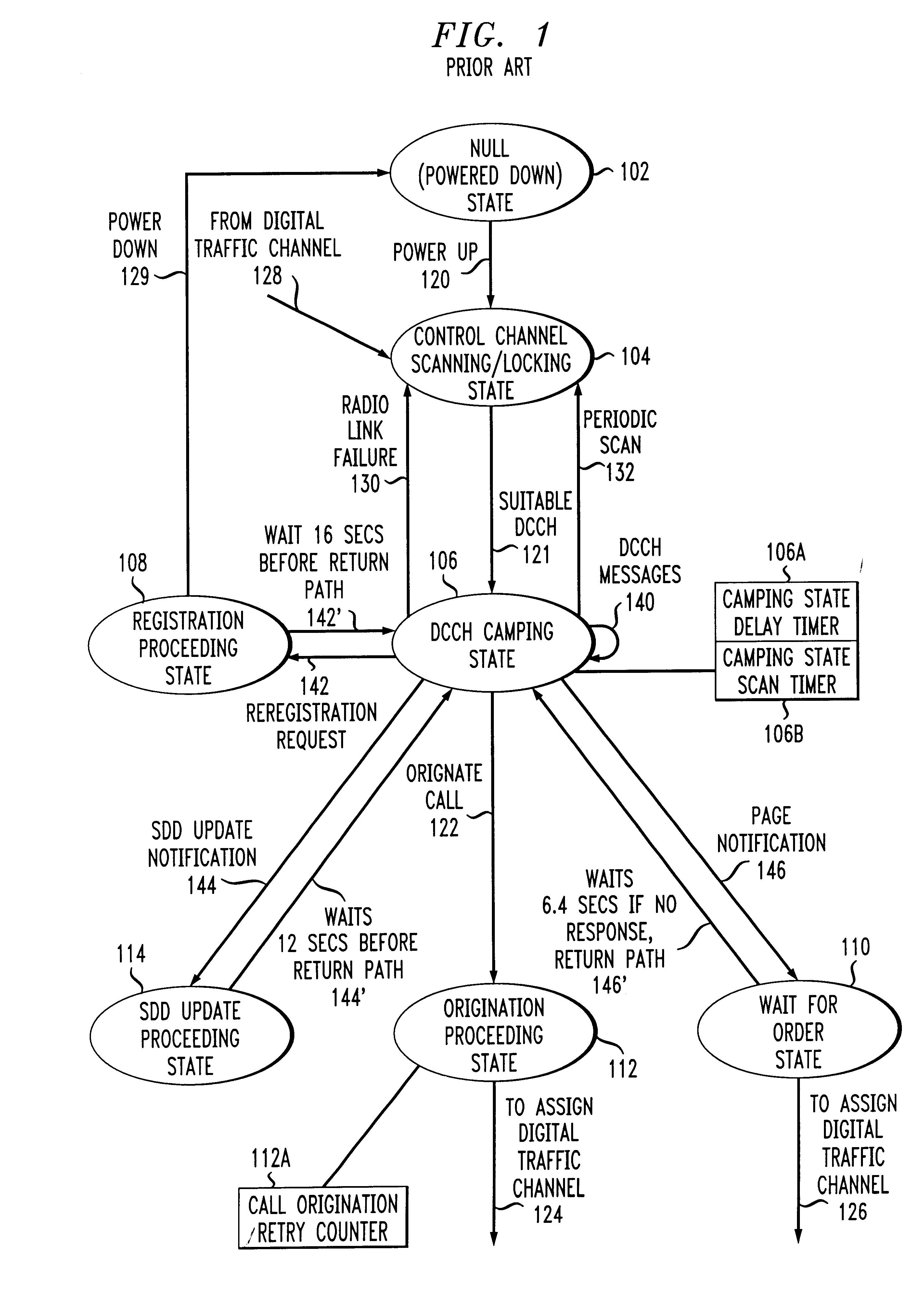
The operation of a wireless mobile device 20 which is registered to a microcell base station 10 is controlled by the base station as shown in the state diagram of FIG. 4, in accordance with the invention. The various states depicted in FIG. 4 are the same as those described for FIG. 1, but the particular control inputs to the states and the application of the responses by the states are modified, in accordance with the invention. The microcell base station 10, transmits digital control channel (DCCH) inputs 140' to the mobile 20 which prevent the mobile 20 from reselecting a control channel while microcell base station 10 does uplink monitoring.

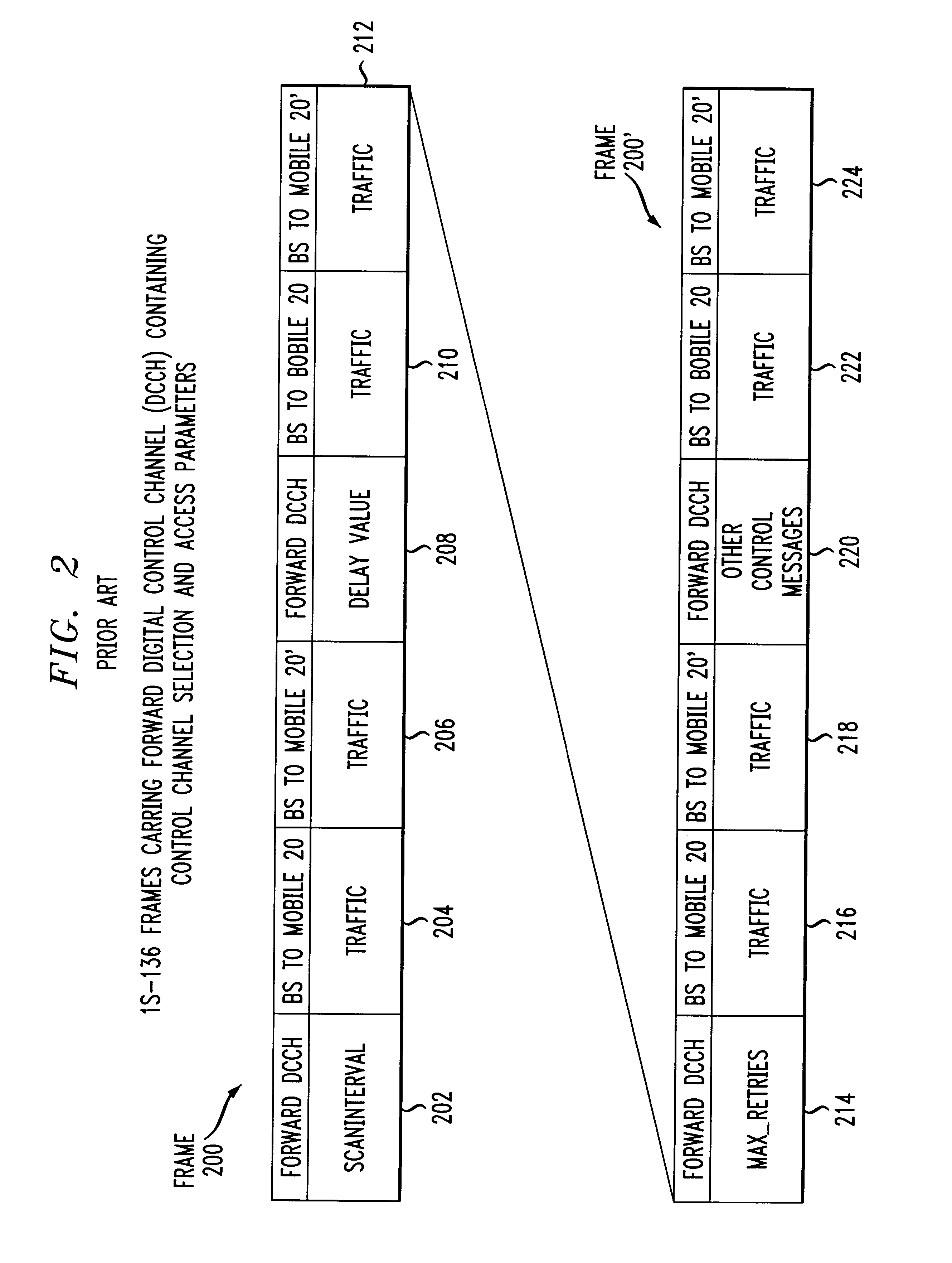
FIG. 5A is a diagram of IS-136 frames carrying forward digital control channel (DCCH) containing messages to set timer and counter values to large values in the mobile device, in accordance with the invention. The frame 200A shown in FIG. 5A contains control channel selection parameters for a larger SCANINTERVAL value in time slot 202A and a ...


PUM


Abstract

Spectrum monitoring measurements are made by microcell base stations in a layered cellular network, while not serving calls or engaged in processing calls. The microcell base station transmits a first control message from to a microcell mobile station, to increase the duration for the mobile station to reside in the camping state on a control channel of the microcell base station. The microcell base station transmits a second control message from the microcell base station to the microcell mobile station, to increase the duration for the mobile station to reside in a call origination state while attempting to access a control channel of the microcell base station. Then, to perform the spectrum monitoring measurement, the base station's transmitter is turned off, the receiver is retuned to the frequency to be monitored, a signal strength measurement taken on that frequency, the receiver is retuned back to its assigned frequency, and the transmitter is turned back on, all in a short time interval. Because the measurement time is so short, it is possible to take spectrum-monitoring measurements without causing inactive mobiles registered on the measuring base station to reselect control channel. Mobiles initiating a call during a spectrum monitoring measurement by its base station are also delayed in their control channel reselection.

Description

1. Field of the InventionThe invention disclosed broadly relates to wireless communications and more particularly relates to RF spectrum monitoring for wireless systems.2. Related ArtThe invention disclosed is related to the copending U.S. patent application Ser. No. 09 / 401,408, filed Sep. 22, 1999, to Mathilde Benveniste, entitled "Self-Configurable Wireless Systems: Spectrum Monitoring In A Layered Configuration", assigned to the AT&T Corporation, and incorporated herein by reference.The invention disclosed is also related to U.S. Pat. No. 5,404,574 to Mathilde Benveniste, issued Apr. 4, 1995, entitled "Apparatus And Method For Non-Regular Channel Assignment In Wireless Communication Systems", assigned to the AT&T Corporation, and incorporated herein by reference.The invention disclosed is also related to U.S. Pat. No. 5,809,423 to Mathilde Benveniste, issued Sep. 15, 1998, entitled "Adaptive-Dynamic Channel Assignment Organization System And Method", assigned to Lucent Technologi...

Claims


Application Information

Patent Timeline
Patent Type & Authority Patents(United States)
IPC IPC(8): H04Q7/20H04W16/14H04W24/00
CPCH04W16/14H04W24/00
Inventor BENVENISTE, MATHILDEPRABHU, SUSHIL KUMAR
Owner AMERICAN TELEPHONE & TELEGRAPH CO
Learn More