Fastening device

a technology of fastening device and fastening ring, which is applied in the direction of snap fasteners, light and heating apparatus, buckles, etc., can solve the problems of complex and difficult assembly of second prior art fastening devices, inability to effectively buckle, and loosening and disengagement of fastening devices, etc., to improve manufacturing efficiency, simplify assembly steps, and reduce costs

Inactive Publication Date: 2004-09-21
LIU A SHENG
View PDF5 Cites 53 Cited by
  • Summary
  • Abstract
  • Description
  • Claims
  • Application Information

AI Technical Summary

Benefits of technology

A primary object of the present is to provide a fastening device for firmly connecting an attached component to a PCB, and includes an elongated body, an operating member and a resilient member. The elongated body penetrates through the attached component and the PCB. The protruding portion is consequently uplifted to force a clipping portion of th

Problems solved by technology

However, the first prior art fastening device cannot effectively buckle the CPU or the heat sink thereto, and the clip 12a becomes loose and disengages when vibrated or impacted.
But the second prior art fastening device is complex and difficult to assemble because of the elongated body 10b first penetrating the positioning

Method used


Image

  • Fastening device
  • Fastening device
  • Fastening device

Examples


first embodiment

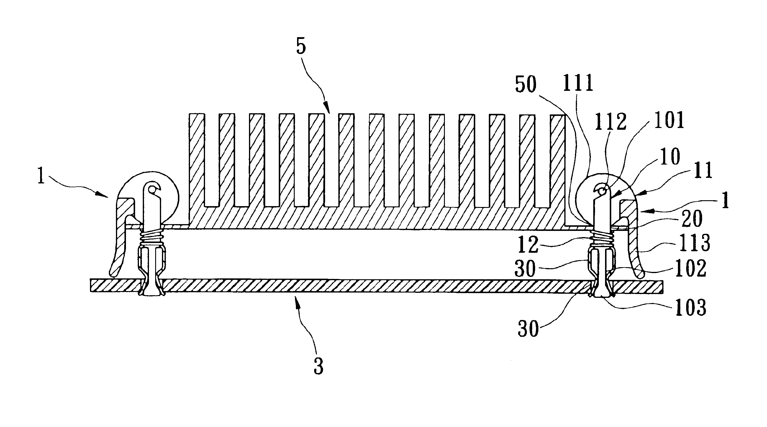
Referring to FIG. 3, which is a decomposed view according to the present invention fastening device, the present invention provides a fastening device 1 adopted for connecting an attached component 2 to a printed circuit board (PCB) 3. The attached component 2 has a positioning hole 20 relative to the fastening device 1, and the PCB 3 has a through hole 30 relative to the positioning hole 20. The fastening device 1 includes an elongated body 10 penetrating through the positioning hole 20 and the through hole 30, an operating member 11 eccentrically pivoted on a top of the elongated body 10, a spring 12 and a resilient member 13 sequently sleeved on an upper half of the elongated body 10. The present invention utilizes pressing the operating member 11 to consequently uplift the elongated body 10, so as to a bottom of the elongated body 10 forces the resilient member 13 in a condition for the resilient member 13 to retain and support horizontally a bottom of the PCB 3 from a condition...

second embodiment

Referring to FIG. 3A, which is the enlarged view according to the present invention fastening device, the pivoted connecting portion 101 includes a through hole formed on the top of the elongated body 10.

third embodiment

Referring to FIG. 3B, which is the enlarged view according to the present invention fastening device, the pressing arm 113 further includes a plurality of patterns 115 protruding from an outer surface thereof for easy manipulation.

Referring to FIG. 4, which is the buckling perspective view according to the first embodiment of the present invention fastening device 1, when the pressing arm 113 is downwardly pushed, the elongated body 10 is consequently uplifted because of the variation of the eccentric shaft 112, such that the protruding portion 103 consequently uplifted relative to the elongated body 10 to force the two clipping portions 131 of the resilient member 13, the two clipping portions 131 thus in a condition for horizontally retaining and supporting the bottom of the PCB 3 in the original condition for vertically contacting the reducing section 102. The present invention fastening device 1 therefore achieves one object of firmly fastening the attached component 2 to the PC...


PUM


Abstract

A fastening device for connecting an attached component to a printed circuit board (PCB) has an elongated body, an operating member and a resilient member. The elongated body penetrates through the attached component and the PCB, and has a reducing section disposed at a lower half thereof and a protruding portion positioned on a free end thereof. The operating member eccentrically pivots to the elongated body, and has an eccentric body and a pressing arm outwardly extending from the eccentric body. The resilient member sleeves on an upper half of the elongated body. The resilient member has a clipping portion disposed at an end thereof and tightly contacting the reducing section. The protruding portion is consequently uplifted to force the clipping portion horizontally supporting a bottom of the PCB while the pressing arm is pushed downwardly, such that the attached component is connected to the PCB.

Description

BACKGROUND OF THE INVENTION1. Field of the InventionThe present invention relates to a fastening device. More particularly, the present invention relates to a fastening device for easily operating and firmly buckling and adopted for mounting a component on a printed circuit board (PCB).2. Description of Related ArtAs computer components develop and electronic devices improve by, for example, increasing of a frequency of a central processing unit (CPU), or enlarging a volume of a heat sink relative to the CPU, a fastening device that is used for firmly mounting the computer components to keep the CPU tight or containing heat dissipation of the heat sink is needed.Referring to FIG. 1, T.W. Patent No 500244 discloses a first prior art fastening device for mounting an attached component 2a tightly on a PCB 3a. The first prior art includes a buckling member 1a, a positioning 20a formed on the attached component 2a, and a through hole 30a formed in the PCB 3a.The buckling member 1a includ...

Claims


Application Information

Patent Timeline
IPC IPC(8): H01L23/40H01L23/34
CPCH01L23/4093H01L2924/0002Y10T24/42Y10T24/44026H01L2924/00
Inventor LIU, A-SHENG
Owner LIU A SHENG
Why Eureka
Try Eureka