Method and apparatus for image representation by geometric and brightness modeling

a technology of geometric and brightness modeling and image representation, applied in the field of image representation, can solve the problems of insufficient high resolution representation, inability to adequately represent high resolution, and inability to capture conventional vectorization methods, etc., to achieve significant reduction in compression, reduce image quality and compression ratio, and reduce the effect of compression

Inactive Publication Date: 2004-10-05
VIMATIX TECH
View PDF11 Cites 10 Cited by
  • Summary
  • Abstract
  • Description
  • Claims
  • Application Information

AI Technical Summary

Benefits of technology

The present invention overcomes the shortcomings of existing image representation techniques based on vectorization. It provides a complete content-oriented representation of high resolution, photo-realistic images. It further provides an efficient tool for mainstream imaging applications, including mathematical model representation without visible distortions of captured images. Furthermore, the representation involves an order of magnitude fewer parameters, having simple visual interpretations, than the number of pixels in the original image.
The computer executable code may further cause the computing device to assemble mathematical models representing the multiple characteristic lines, the visual relationships and the background, respectively. The mathematical models representing the characteristic lines are then aggregated with the mathematical models representing the visual relationships among the characteristic lines and the background of the image. The computer executable code may store data representing the mathematical models representing the characteristic lines, the visual relationships and the background in the at least one data storage device.

Problems solved by technology

In other words, they fail to adequately represent high resolution, photo-realistic images of the real world.
In contrast, high resolution, real world pictures present an enormous variety of forms and highly complex visual patterns, which conventional vectorization methods fail to capture.
In fact, high resolution, real world images present such an enormous variety of forms and complex visual patterns, that visually accurate vectorization is practically impossible under the existing methods.
Although the existing methods of image representation, processing and compression, such as DCT transform and the JPEG compression standard, as well as various wavelets transforms and compression schemes, may satisfy the first requirement above, they fail with respect to the remaining four requirements.
Subsequent quantization and filtering reduces the number of parameters, but in an unpredictable fashion.
Also, visual interpretation of the reduced number of parameters may be difficult.
Moreover, because video sequences represent exactly the motion of certain objects and patterns (i.e., geometric transformations of the initial scene), the DCT or the wavelets representations of video sequences behave in an incoherent and unpredictable manner.
This results in a tremendous reduction in efficiency.
Although providing additional efficiency to image representation and processing in the "geometric image domain," the disclosed method does not solve the main problems of the existing methods.
Furthermore, the method does not include any tools for representing background and texture visual patterns.
The geometric accuracy of the suggested edge detection method (i.e., marking the nearest pixel and edge direction) is not sufficient for a faithful image reconstruction.
However, the visual quality and compression ratio is low and image processing on the compressed data is impractical.
However, the image quality and resolution are not sufficient for most practical applications, the compression ratio is inferior to that of other conventional methods and processing the compressed data is cumbersome and complicated.
Other practical disadvantages of the invention disclosed in the U.S. Pat. No. 5,510,838 include the following: (i) the image is subdivided into cells of a size of 6 to 48 pixels, which cells are represented independently, thereby reducing image quality and the compression ratio; (ii) there is no accounting for visual adjacencies between the models; (iii) approximation of edges and ridges by polygonal lines causes visual degradation (e.g., a "staircase effect"); (iv) the resolution of the detection method is insufficient due to second degree polynomial approximations on 4.times.4 pixel windows; (v) representation of the background is unstable and inefficient, resulting in visual degradation of the image, low compression and cumbersome processing; and (vi) the only tool for representing background textures, which are areas of dense fine scale patterns of low visual significance, is combining a large number of hills, resulting in visual degradation and significant reduction in compression, especially for images with rich textures.
However, U.S. Pat. No. 5,960,118 did not eliminate the necessity of subdividing images into cells of 6 to 48 pixels.
Also, representation of background and textures is still problematic.
One major problem continues to be that the conventional methods only provide a "semi-local" image representation based on mathematical models and fail to provide "global" representation of the entire image.
Dissecting the image into independent blocks causes significant disadvantages and significantly reduces processing efficiency.
The artificial separation of the image into cells is detrimental in all applications of vectorized images.
Moreover, splitting edges and ridges into segments precludes the possibility of taking into account global geometric correlations of data along these curves.
This introduces complicated geometric patterns, which are completely irrelevant to the original image.
This may result in different quantizations of color and geometric parameters in adjacent cells, which result in visual discontinuities between the adjacent cells even for relatively fine quantization steps.
All conventional representation methods based on cell subdivision, share this disadvantage.
Also, separation into cells negatively affects geometric transformations.
This procedure is complex and often fails in the initial stages, making geometric processing of cell subdivisions virtually impossible.

Method used


Image

  • Method and apparatus for image representation by geometric and brightness modeling
  • Method and apparatus for image representation by geometric and brightness modeling
  • Method and apparatus for image representation by geometric and brightness modeling

Examples


Embodiment Construction

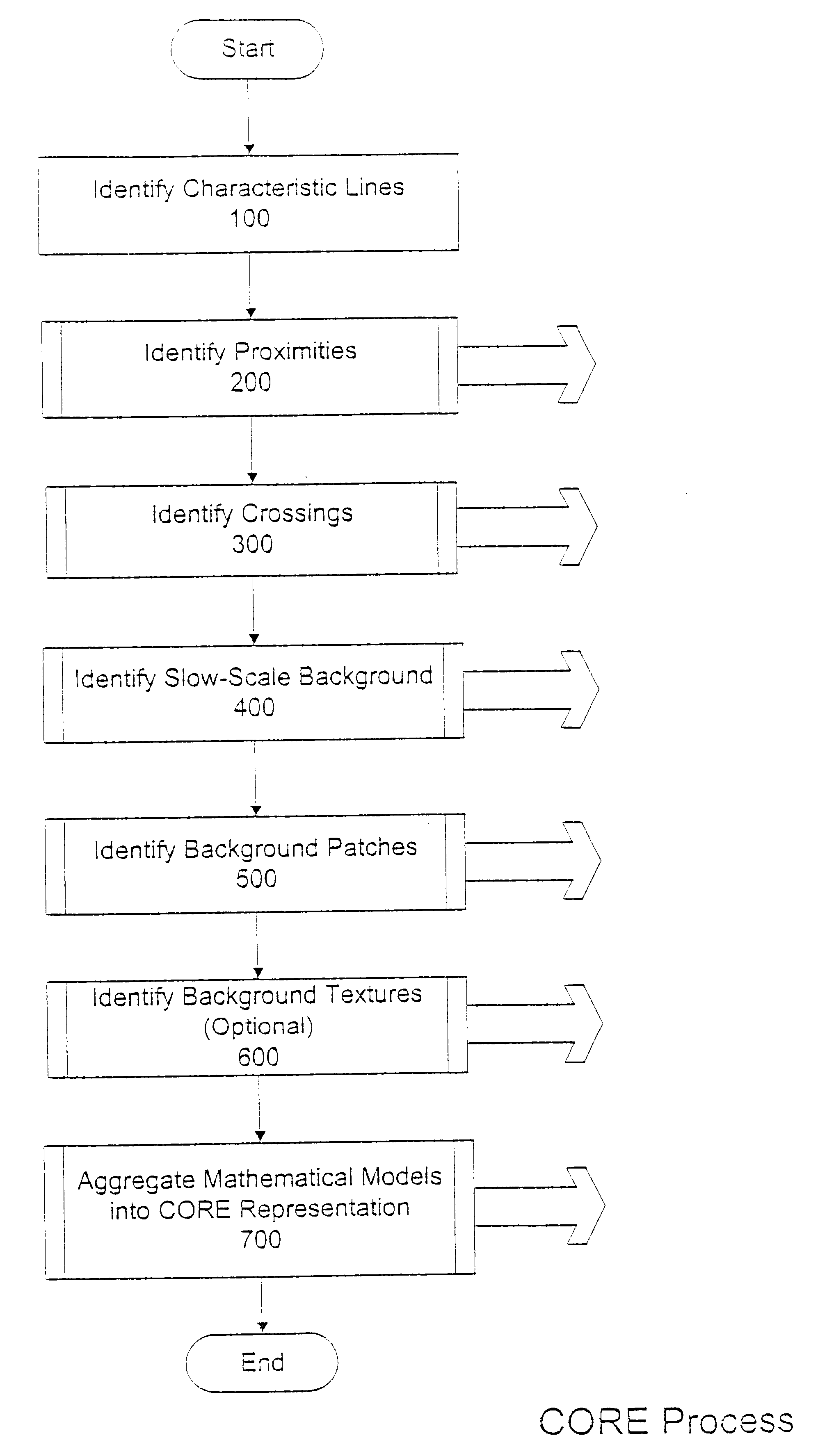
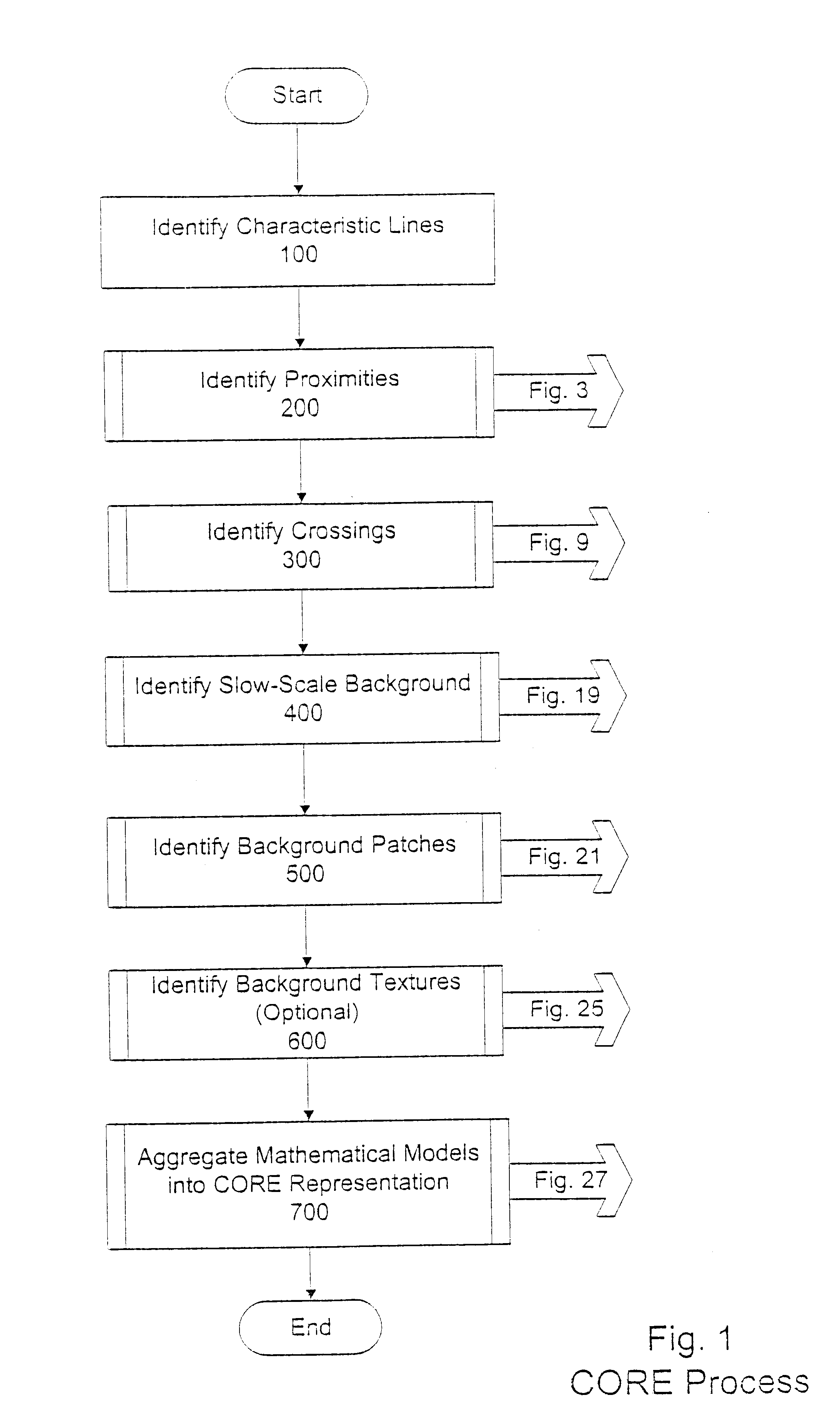
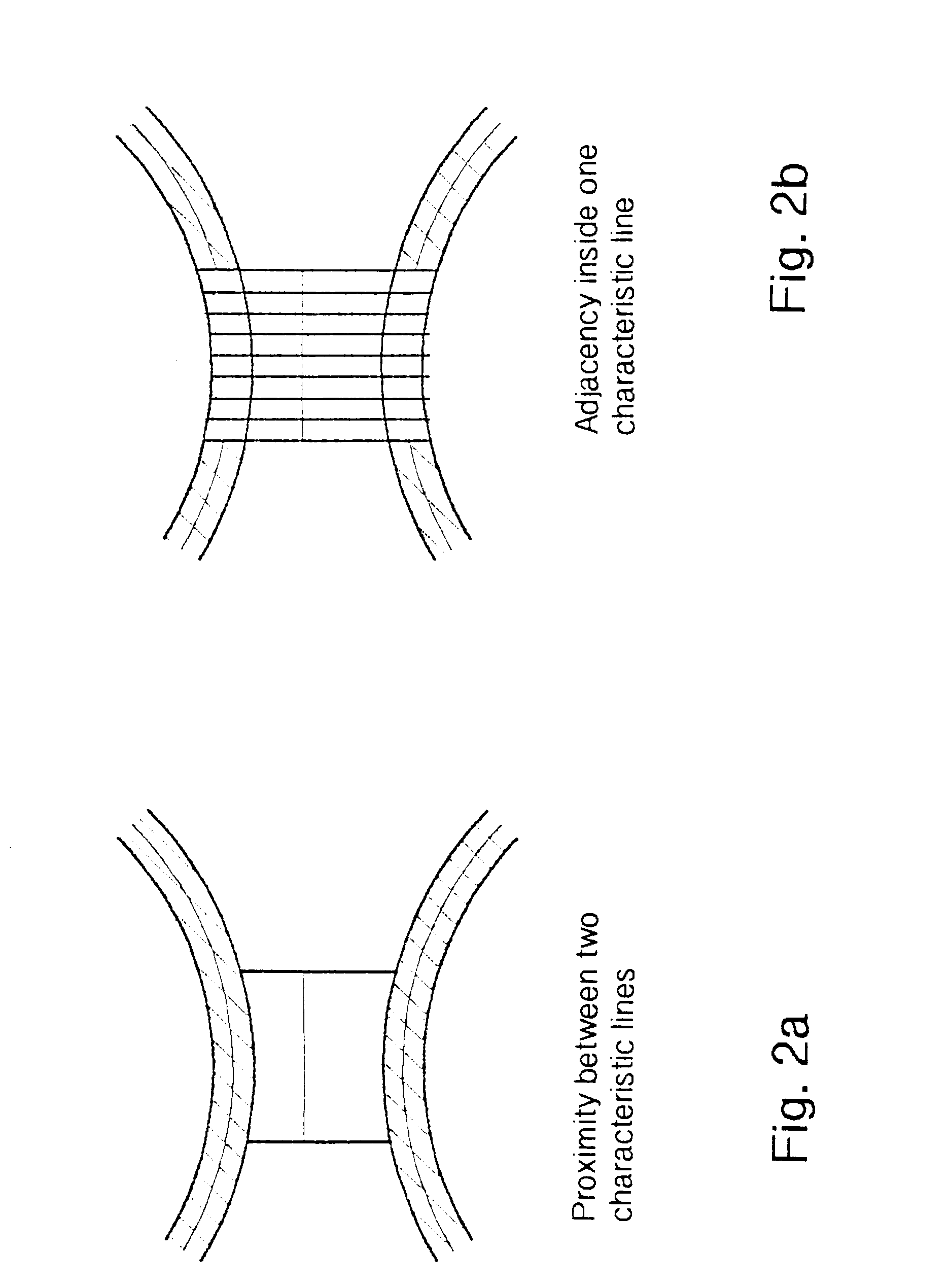
The present invention is a method and apparatus for representing digital images as mathematical models. In particular, the invention relates to using the identified characteristic lines and associated parameters of an image, including characteristic strips, signatures, cross-sections and transformations, as the basis for determining the content-oriented representation ("CORE") parameters, which transform the image into a globalized mathematical model. The CORE process includes identifying proximities and crossings of characteristic lines; identifying the background, including the slow-scale background, patches and textures; and aggregating the mathematical models derived from the image. A CORE represented image is accurately and efficiently reproducible based on these mathematical models.

Different types of images are processed according to the present invention, originating from different sources. Types of images include, for example, black and white and color images produced by dig...


PUM


Abstract

A method for representing an image includes identifying characteristic lines of the image and the visual relationships among the characteristic lines. The visual relationships include proximities and crossings of the characteristic lines. The method further includes defining a background of the image, the background including a slow-scale background, background patches and background textures. Mathematical models representing the characteristic lines, the visual relationships among the characteristic lines and the background, respectively, are assembled and aggregated.

Description

BACKGROUND OF THE INVENTION1. Field of the InventionThe present invention relates to the field of image representation. More particularly, the present invention relates to a method of representing images using mathematical models of geometric and brightness characteristics of the image, known as Content Oriented Representation ("CORE").2. Background InformationAnalysis and processing of digital images play an important role in nearly all disciplines of modern industry and economic activity. From medical imaging to industrial quality control and diagnostics, to entertainment and advertising, efficient image analysis, representation and processing is the primary component of overall imaging system performance.Presently, there are forms of content-oriented representation of images known in the field of image representation. Partial implementations exist, known generally as "vector formats" and "vectorizations," which are representations of visual images by geometric entities, such as v...

Claims


Application Information

Patent Timeline
Patent Type & Authority Patents(United States)
IPC IPC(8): G06T5/00G06T15/40G06T17/00G06T15/10G06T15/00G09G5/00H04B
CPCH04B1/52G06T7/0085G06T2207/20144G06T7/13G06T7/194
Inventor YOMDIN, YOSEFELICHAI, YORAM
Owner VIMATIX TECH
Why Eureka
Try Eureka