Parallel redundant power system and method for control of the power system

a power system and power system technology, applied in the direction of dc-ac conversion without reversal, emergency power supply arrangement, transportation and packaging, etc., can solve the problems of single ups device not being able to meet the electricity requirement, and affecting the operation of the power system

Active Publication Date: 2004-10-12
PHOENIXTEC POWER
View PDF7 Cites 74 Cited by
  • Summary
  • Abstract
  • Description
  • Claims
  • Application Information

AI Technical Summary

Problems solved by technology

Especially in the present age where a breathtaking variety of electronic products are widely used, serious economic loss may possibly occur if a company loses critical data when the electricity supply is suddenly interrupted.
However, because of the quick evolvement of the load specifications, a single UPS device may be unable to satisfy the electricity requirement, especially when the amount of the loads is increased.
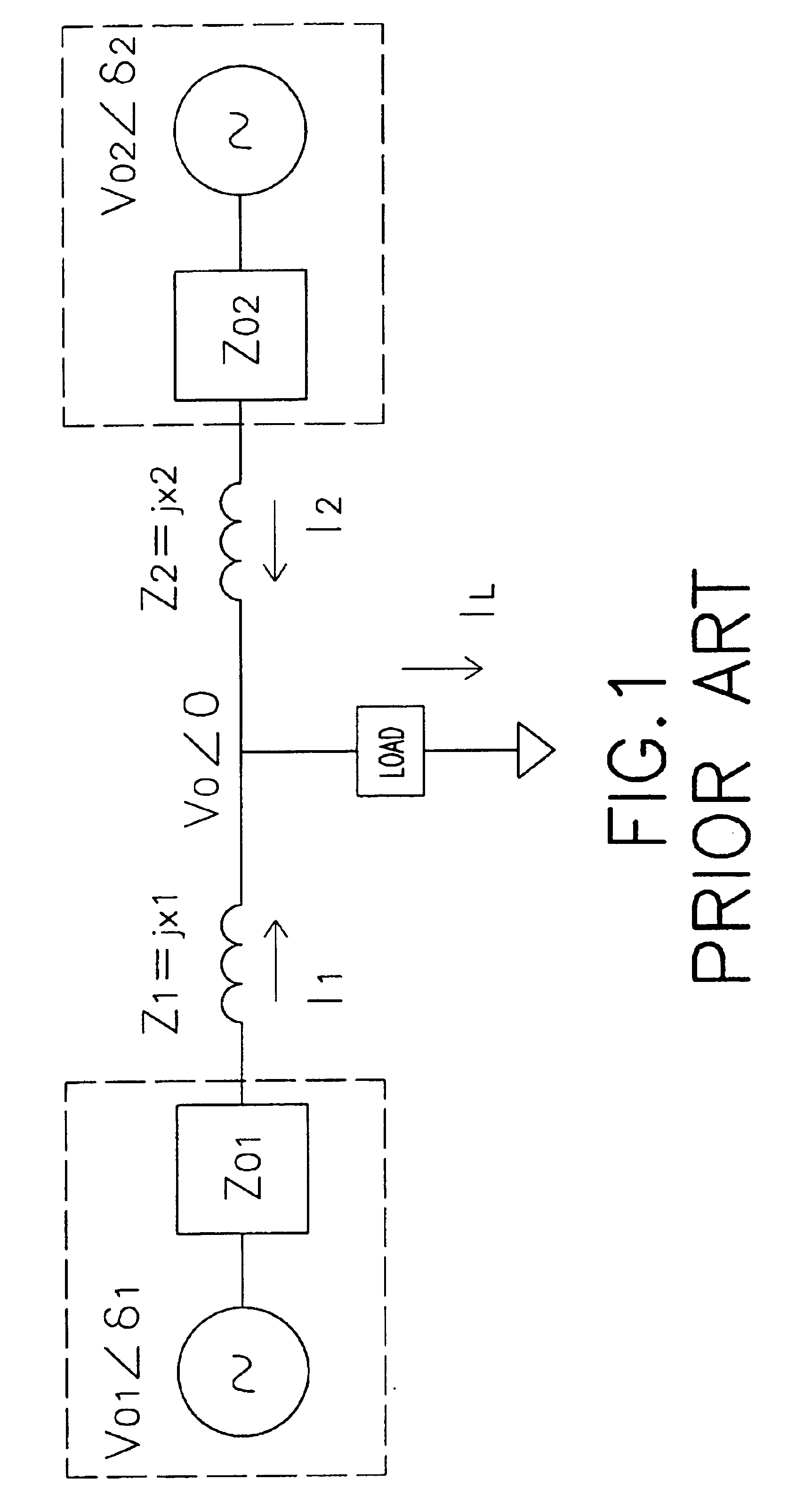
In U.S. Pat. No. 5,745,356, only the DC energy is calculated and only the differentiation of the active power is concerned; however the reactive power is difficult to control.
The differentiation manner in the prior art has some further drawbacks, such as the low anti-interference ability and being unable to process harmonic waves.
Further, with regard to the active power and the reactive power, U.S. Pat. No. 6,118,680 can not provide an efficient control manner.
Since the inductor is composed of windings, the entire size and weight of the UPS system will become extremely large and heavy if the inductor is coupled to the output of the UPS module.
Moreover, when the load is coupled to the UPS system, the impedance of the inductor will interfere with the output voltage adjustment accuracy of the UPS system.
However, some necessary requirements such as the function of the parallel connectionless operation, the volume and weight of the UPS module, and the output adjustment accuracy etc. will be hard to be satisfied.

Method used


Image

  • Parallel redundant power system and method for control of the power system
  • Parallel redundant power system and method for control of the power system
  • Parallel redundant power system and method for control of the power system

Examples


Embodiment Construction

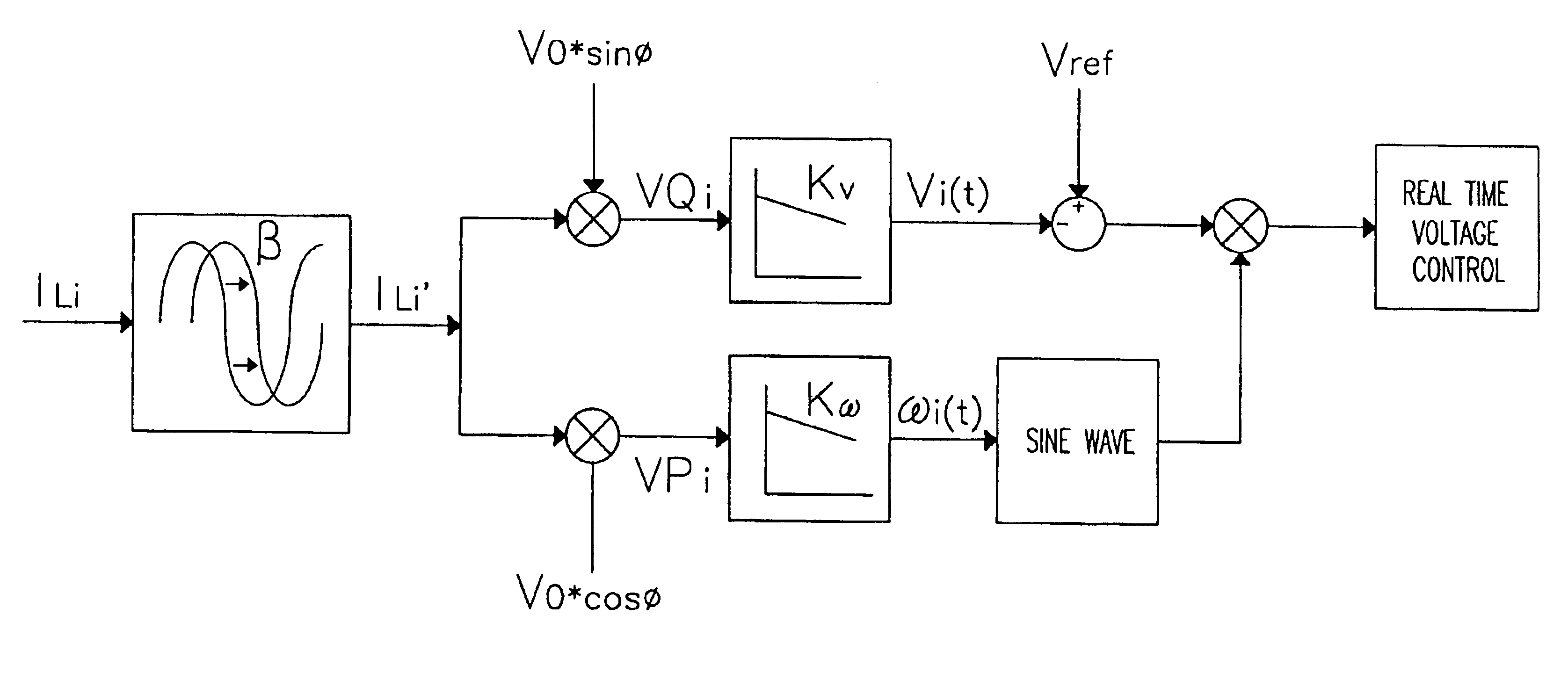
With reference to FIG. 4, a parallel redundant UPS system is composed of multiple UPS modules (10)(101-10N) connected in parallel. If the output power of each UPS module (10)(101-10N) is high, all UPS modules (10)(101-10N) are coupled in parallel and through a power output distributor (POD)(20) to provide the combined power to a load. Otherwise, if the output power of each UPS module (10)(101-10N) is low, all the UPS modules (10)(101-10N) can coupled together via wires and then collectively provide the power to the load without the use of the POD (20). It should be noted that the present invention does not only apply to the parallel connected UPS modules, but also can control parallel connected AC inverters.

For each UPS module (10)(101-10N) in FIG. 4, the input voltage and the output voltage both are single phase (R-phase) in this embodiment. It should be noted that the present invention is able to be applied on a power system with more than one phase AC input and output voltage. Fo...


PUM


Abstract

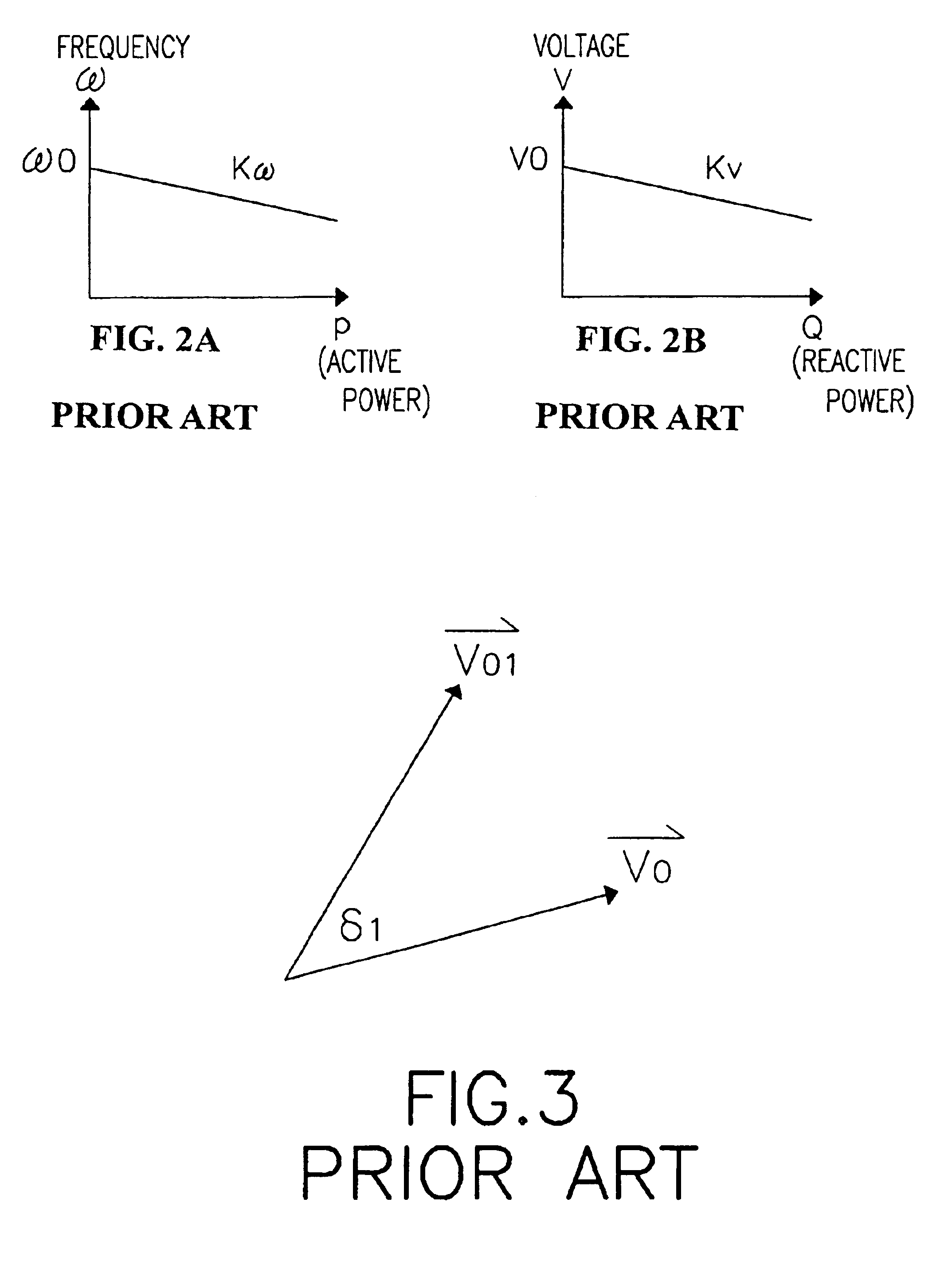
A parallel redundant power system and a method for control the same, wherein the power system is composed by UPS modules with outputs coupled in parallel to supply power to a load through a bus. The control method employs the P-omega and Q-V slope lines of the droop method to perform phase locking and current sharing. Moreover, the method further utilizes the internal impedance of the UPS in accompaniment with a current shift method to simulate an actual inductor being coupled to the output of the UPS module so as to satisfy the droop method. Therefore, the drawbacks otherwise caused from actual inductors such as the large size and heave weight are eliminated.

Description

1. Field of the InventionThe present invention is related to a method for controlling a parallel redundant power system composed of UPS modules coupled in parallel, and more particularly to a method that utilizes the internal impedance of the UPS modules in accompaniment with a current shift method to simulate a virtual inductor so that the drawbacks caused from the actual inductor are eliminated.2. Description of Related ArtsWith the almost total-dependence of modern societies on electricity for employment, living, communication and entertainment, any disruption to an electricity supply brings about a temporary halt to civilization as we know it. Especially in the present age where a breathtaking variety of electronic products are widely used, serious economic loss may possibly occur if a company loses critical data when the electricity supply is suddenly interrupted.To solve the above problem, the uninterruptible power supply (UPS) is developed. However, because of the quick evolv...

Claims


Application Information

Patent Timeline
Patent Type & Authority Patents(United States)
IPC IPC(8): H02J3/44H02J3/46H02M7/48H02J3/40H02J9/06H02M7/493
CPCH02J3/44H02M7/493H02J3/46H02J9/062H02J3/466
Inventor LUO, HAN-SHENGTIAN, SHOU-LONGTSAI, CHIA-MING
Owner PHOENIXTEC POWER
Why Eureka
Try Eureka