The
gradation from dark to light breaks up the surface of an object and makes it harder to see the object as one thing.
However, strategies based on natural observations often fall short of military requirements.
First, animal coloration is often idiosyncratic and keyed to narrow co-evolution histories of predator and prey in a specific econiche--that is, the zebra's stripes tell us more about the
visual system of the lion than about
usable principles of military camouflage.
Second, organisms are limited in the strategies (patterns) they can "employ."
However, animals do not "design" their appearance; the process is passive and represents genetic exploitation of random mutations.
Biological entities have the
disadvantage of not being able to produce an animal with both spots and stripes, or with complex patterns of certain types.
The problem of disrupting the human form in both the near-
infrared and visible ranges is only a military problem that has no parallel in the natural world.
Adding to the complexity is that dry and wet conditions change
reflectivity of surfaces changing the "hiding" characteristics of most patterns under different light conditions.
Also, experience showed that most camouflage measures simply did not work very well.
Some of these designs had little practical counter-surveillance utility, but looked somehow "martial."
For military applications, color is an additional issue that must be considered.
Two significant deficiencies common to most camouflage pattern measures is that most pattern measures address either the configuration of the target to be hidden, or the nature of the background into which the target must blend.
This limits the usefulness and robustness of a concealment measure since both objectives must be answered if the target's signature is to be significantly reduced for the observer.
The issue with mimic patterns is that they are site specific or geographically limited.
For military applications, the mimic of a particular setting is inadequate.
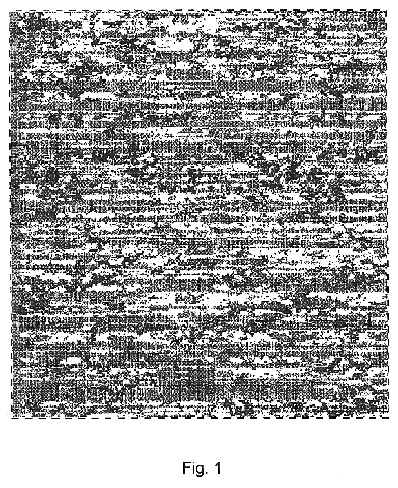
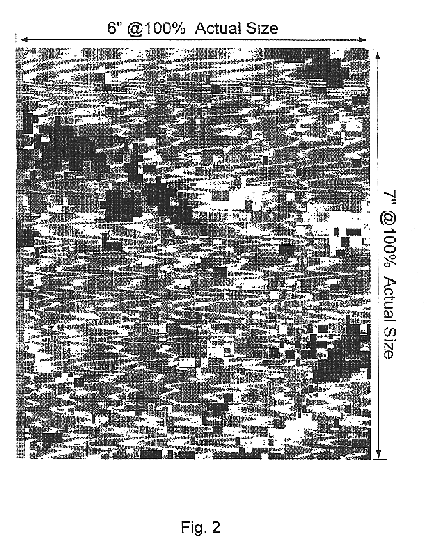
The result was a macropattern that disrupted the shape of the target making it hard to recognize, and a micropattern that matches the texture of the background, making it hard to detect (hence "Dual-Texture").
No previously known or currently known camouflage pattern measure appears to address both these factors (disrupting the target and matching the background) effectively for a
broad spectrum of
terrain and environmental conditions needed for military
operational effectiveness.
Field-testing revealed that none of the existing patterns provide maximum concealment possible given today's printing and material technologies as well as pattern concepts.
These types of fabrics were hot to wear, became heavier when wet and were slow to dry.
Finding the correct balance of
fiber composition, weave, weight, and ability to take the needed dyes was a complicated empirical problem.
While there are numerous types of dyes and pigments, all of which are chemically compatible with specific
fiber types, they can not be used interchangeably.
Acid dyes are compatible with
nylon fiber and are very colorfast, but in the near
infrared, generally, they are too light and bright for military camouflage purposes.
They are very colorfast, but in the near infrared, generally, they are too dark.
Disperse dyes are compatible with
polyester, however, they are not available in the colors required to meet military camouflage specifications, they are not very colorfast, and they are light and bright in the near infrared.
A problem still remains.
The problem is achieving the objectives of a durable, serviceable uniform with concealing characteristics in the visible and near infrared.
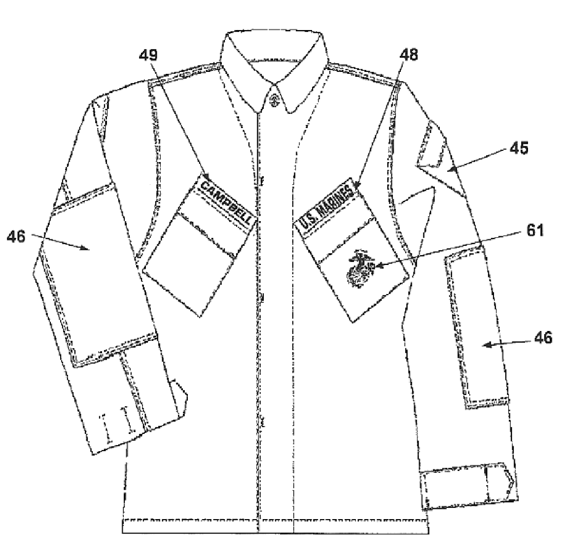
Through focus group discussion and feedback to the uniform board, the United States Marine Corps (USMC) found that the current curved style camouflage patterned uniform was inadequate for color, pattern, and durability of the fabric.
Additionally, there were other problems.
This is an issue that concerned many Marines because the change in color can markedly change the hiding ability of the disruptive pattern.
The inventors found that while camouflage patterns can be described by mathematics after the fact, it is not possible to design a pattern by formula alone.
When applied to uniforms (clothing) design becomes more difficult because the shape is always changing as a subject moves.
Obviously, there is a pixel size too small to be resolved at tactical distances.
Although these shapes have relatively sharp edges, the line can be jagged and not long straight lines.
However, if the line is not smooth but is irregular and jagged, its measured length will depend on the length of the ruler used.
It is also possible to use
image analysis techniques to define sub configurations based on the physical characteristics of the environment, but this is not necessary in most cases, and might lead to nonproductive excursions into artistic
mimicry.
While alone each
fiber and dye combination will not provide the desired near infrared performance, together they synergistically provide the desired performance.
Existing
polyamide blend combat uniform fabrics do not provide durable electrostatic dissipation protection.
Other fiber types and blends do not provide the durability and colorfastness properties obtained with acid and vat dyes and do not provide the same level of visual and near-infrared camouflage protection.
Other colorants or dyestuffs such as pigments, direct dyes, fiber reactive dyes, etc. could be used but would not provide the critical
reflectivity and colorfastness properties needed in military clothing items.
Velcro (hook & loop) type closures are not suitable for military use because they make too much
noise but are acceptable in civilian or hunter sportsman type environments.

