Laser clad knife guard

Inactive Publication Date: 2016-03-17
KONDEX CORP
View PDF3 Cites 2 Cited by
  • Summary
  • Abstract
  • Description
  • Claims
  • Application Information

AI Technical Summary

Benefits of technology

[0007]The present invention is generally directed towards cladding the knife guard in one or more select regions. Cladding may be deposited on an entire top surface of a ledger bar to improve the wear characteristics of the ledger bar. Additionally or alternatively, the cla

Problems solved by technology

Past efforts to improve the hardness of the shearing surfaces of the ledger plate have not met with the desired cutting efficiency or wear characteristics which in turn have resulted in increased costs in both harvesting and equipment repair and or replacement.
Distortion is not desirable where the knife guard provides a bearing surface supporting sliding movement and reciprocation of a sickle bar.
The result is often additional machining or straightenin

Method used


Image

  • Laser clad knife guard
  • Laser clad knife guard
  • Laser clad knife guard

Examples


Example

[0044]While the invention will be described in connection with certain preferred embodiments, there is no intent to limit it to those embodiments. On the contrary, the intent is to cover all alternatives, modifications and equivalents as included within the spirit and scope of the invention as defined by the appended claims.

DETAILED DESCRIPTION OF THE INVENTION

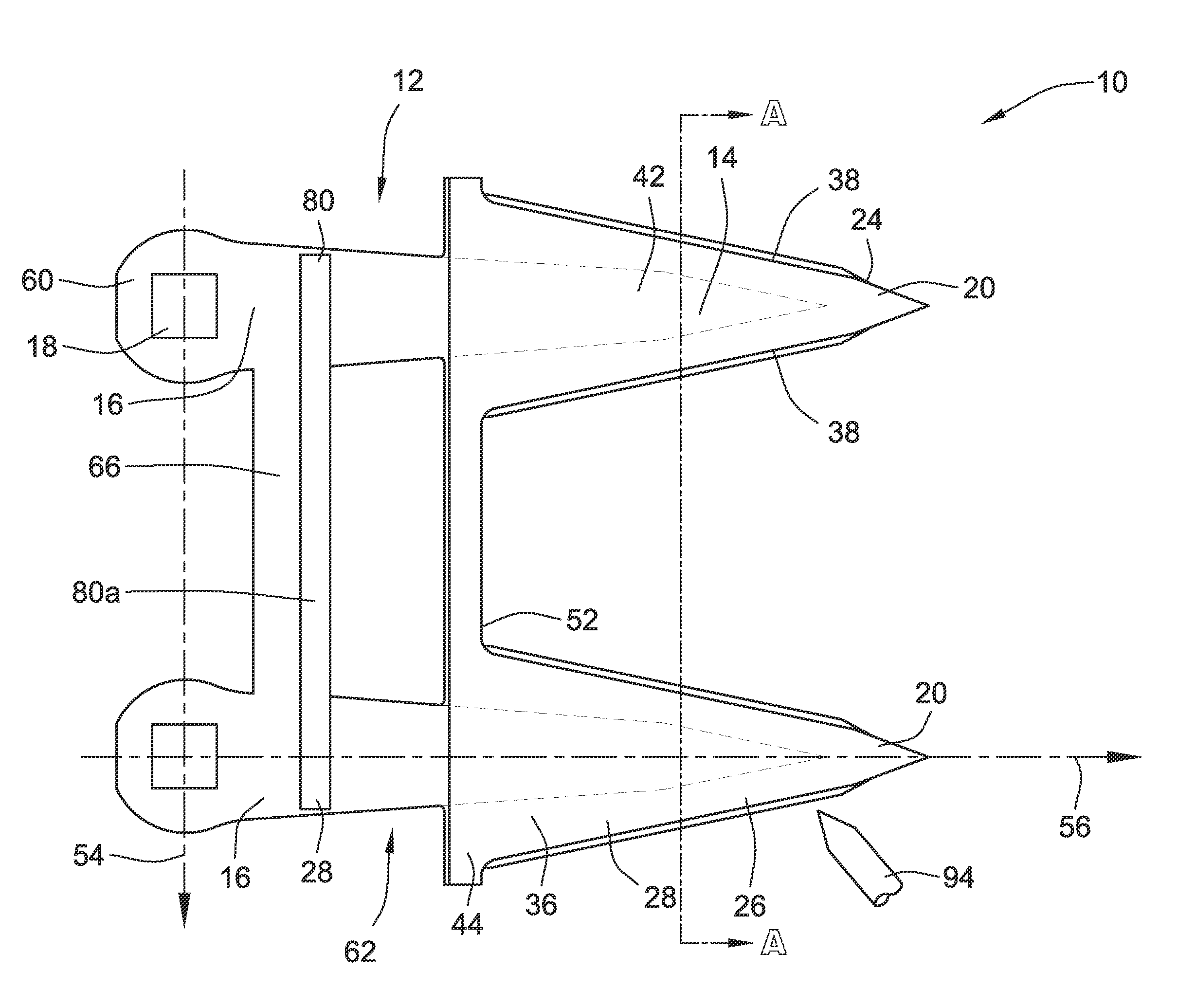
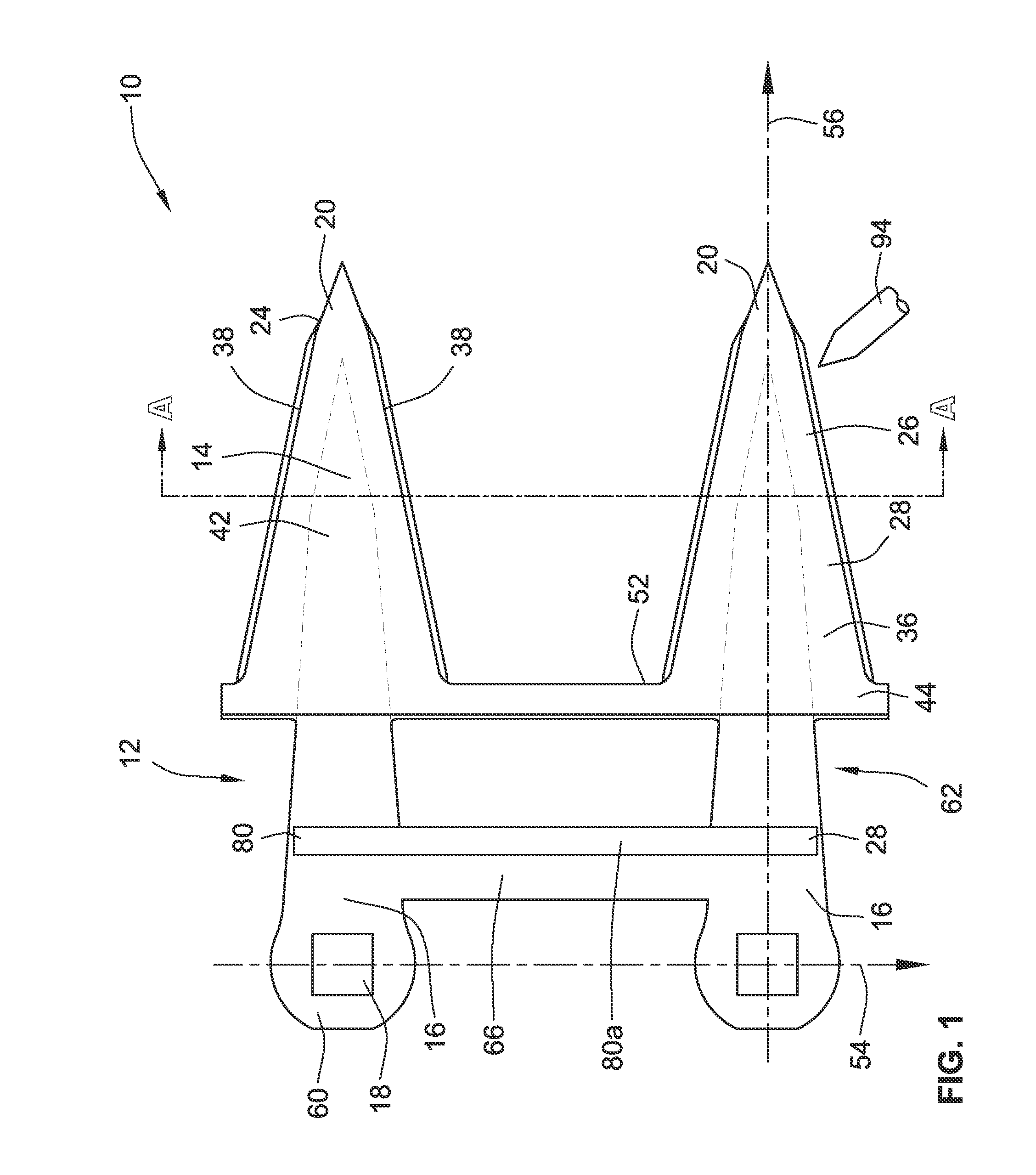
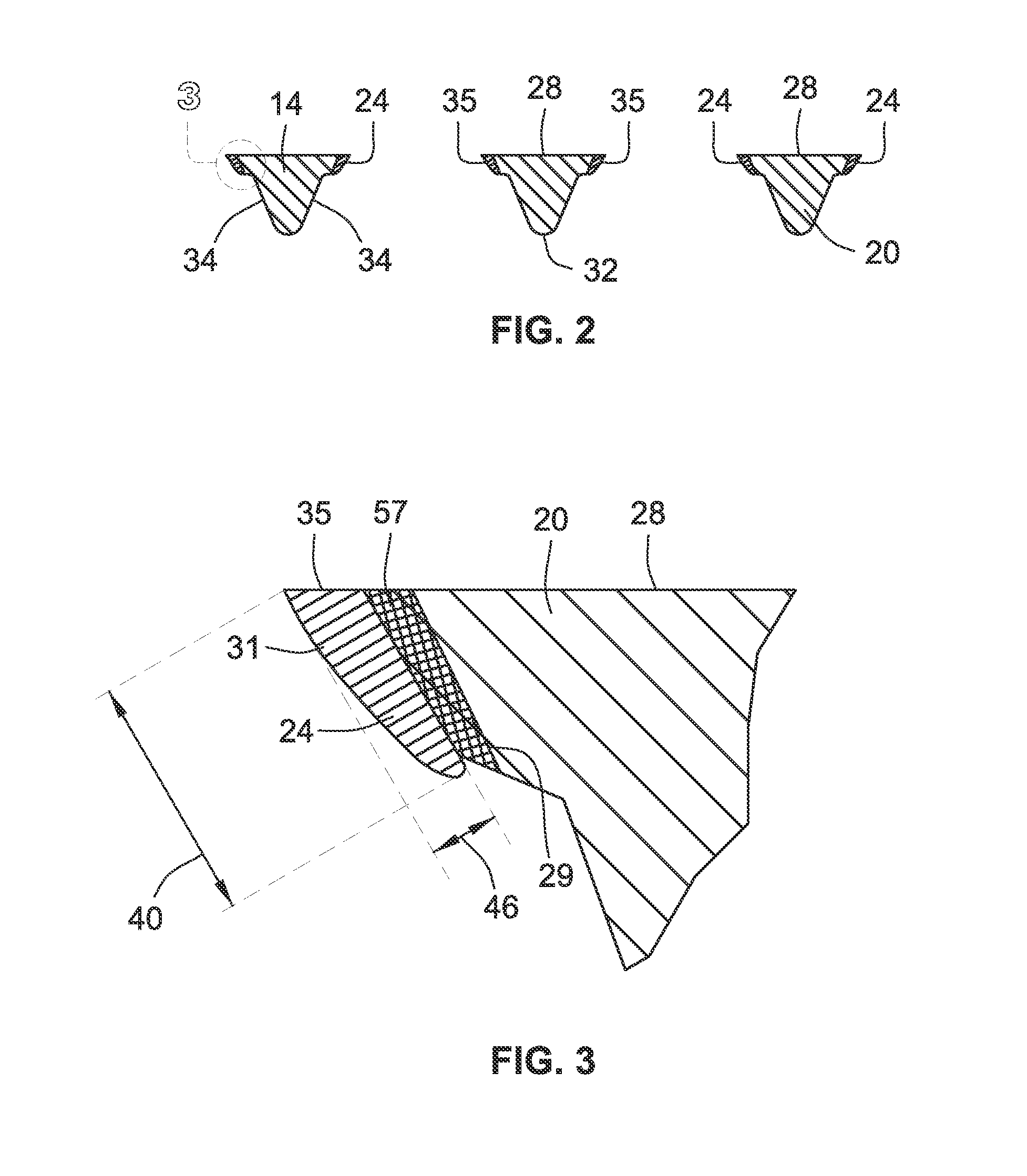
[0045]As shown in FIG. 1, a laser clad knife guard 10 according to an embodiment of the present invention is illustrated. A knife guard 10 comprises a guard body 12 and is comprised of a base material 14 such as steel material, that includes a mounting bar 16, which defines at least one bolt hole 18 and at least one tine 20 projecting forward 56 from the mounting bar 16. The base material 14 has a first hardness 22 and a clad material 24 is deposited on the base material. The clad material 24 comprises a second hardness 26, greater than the first hardness 22 and can be deposited in horizontal strips running lengthwise from a r...


PUM

PropertyMeasurementUnit
Fractionaaaaaaaaaa
Fractionaaaaaaaaaa
Fractionaaaaaaaaaa

Abstract

A cladded knife guard is provided. In one aspect, the invention provides for a knife guard that comprises a guard body that further comprises a base material. The base material includes a mounting bar that defines at least one bolt hole and at least one tine projecting forward from the mounting bar. The base material has a first hardness. A cladded material is formed on the base material. The clad material comprises a second hardness greater than the first hardness.

Description

CROSS-REFERENCE TO RELATED PATENT APPLICATIONS[0001]This patent application is a continuation of co-pending PCT Application No. PCT / US2015 / 018059, filed Feb. 27, 2015, which claims the benefit of U.S. Provisional Patent Application No. 62 / 050,687, filed Sep. 15, 2014, and U.S. Provisional Patent Application No. 62 / 050,880, filed Sep. 16, 2014, the entire teachings and disclosure of which are incorporated herein by reference thereto.FIELD OF THE INVENTION[0002]This invention generally relates to a laser clad knife guard for a sickle bar assembly.BACKGROUND OF THE INVENTION[0003]Knife guards are used in sickle style cutting systems. They act as the stationary surface for moving sickle blades to cut against or at least to protect or cover the sickle blades. Examples are shown in U.S. Pat. Nos. 6,962,040, 4,660,361, 7,478,522, and 8,464,506 the disclosures of which are incorporated by reference as the present invention may be applied and / or incorporated into these examples in various em...

Claims


Application Information

Patent Timeline
IPC IPC(8): A01D34/18A01D34/14B23K26/34
CPCA01D34/18B23K26/34A01D34/14B23K2101/20
Inventor STOFFEL, NEAL, J.
Owner KONDEX CORP
Why Eureka
Try Eureka