
Motion and audio detection based webcamming and bandwidth control

a technology of motion and audio detection and bandwidth control, applied in the field of multimedia devices, can solve the problems of wasting resources, continuous uploading of video frames to the web server, and conventional web cam systems continuously upload video frames, and achieve the effect of maximizing the use of system and network resources

Inactive Publication Date: 2004-11-02
LOGITECH EURO SA
View PDF23 Cites 54 Cited by
  • Summary
  • Abstract
  • Description
  • Claims
  • Application Information

AI Technical Summary

Benefits of technology

The present invention is a video and audio processing system for transmission of video and audio frames across a network. The system includes a video input mechanism, motion detection mechanism, and web cam mechanism. The video input mechanism receives a first video frame and a second video frame, with the first frame serving as a reference frame. The motion detection mechanism compares the first frame with the second frame and generates a motion-detected signal if there is a deviation between the two frames. The web cam mechanism transmits the non-reference video frame to the network if there is a motion detection signal. The system also includes a method for processing video frames by comparing them with a reference frame and determining if there is sufficient motion to warrant transmitting the frame. The system and method save computing system resources by processing and transmitting only frames that meet a certain threshold requirement for motion detection. This reduces network bandwidth consumption and flexibility in setting parameters for transmitting frames based on bandwidth availability.

Problems solved by technology

One problem with conventional web cam systems are continuous uploading of video frames to the web server despite no video viewers downloading the video frames for prolonged periods of time, if at all.
Another problem is that conventional web cam systems continuously upload video frames despite no change occurring between the content captured within one video frame to another video frame.
In each described instance, it is clear that conventional web video cameras conventional web cam systems waste resources such as network bandwidth, computing system resources, and electrical power to transmit video frames that have no viewership or no change in content from one video frame to another.
A significant problem with conventional peer-to-peer video systems includes the need for a large quantity of bandwidth to transmit the video frames back and forth between the two computers.
Yet another problem with this approach is that bandwidth capacity may be severely limited by the network connection (e.g., a 56 kbps modem connection) so that unnecessary transmission of video frames results in lost video frames and / or degraded video transmission.
Thus, similar to conventional web video cameras used in conventional web cam systems, conventional web video cameras used in conventional peer-to-peer video systems also unnecessarily diminish limited network bandwidth and unnecessarily draw and use computing system and electrical power resources to transmit its video frames.

Method used


Image

  • Motion and audio detection based webcamming and bandwidth control
  • Motion and audio detection based webcamming and bandwidth control
  • Motion and audio detection based webcamming and bandwidth control

Examples


Embodiment Construction

)

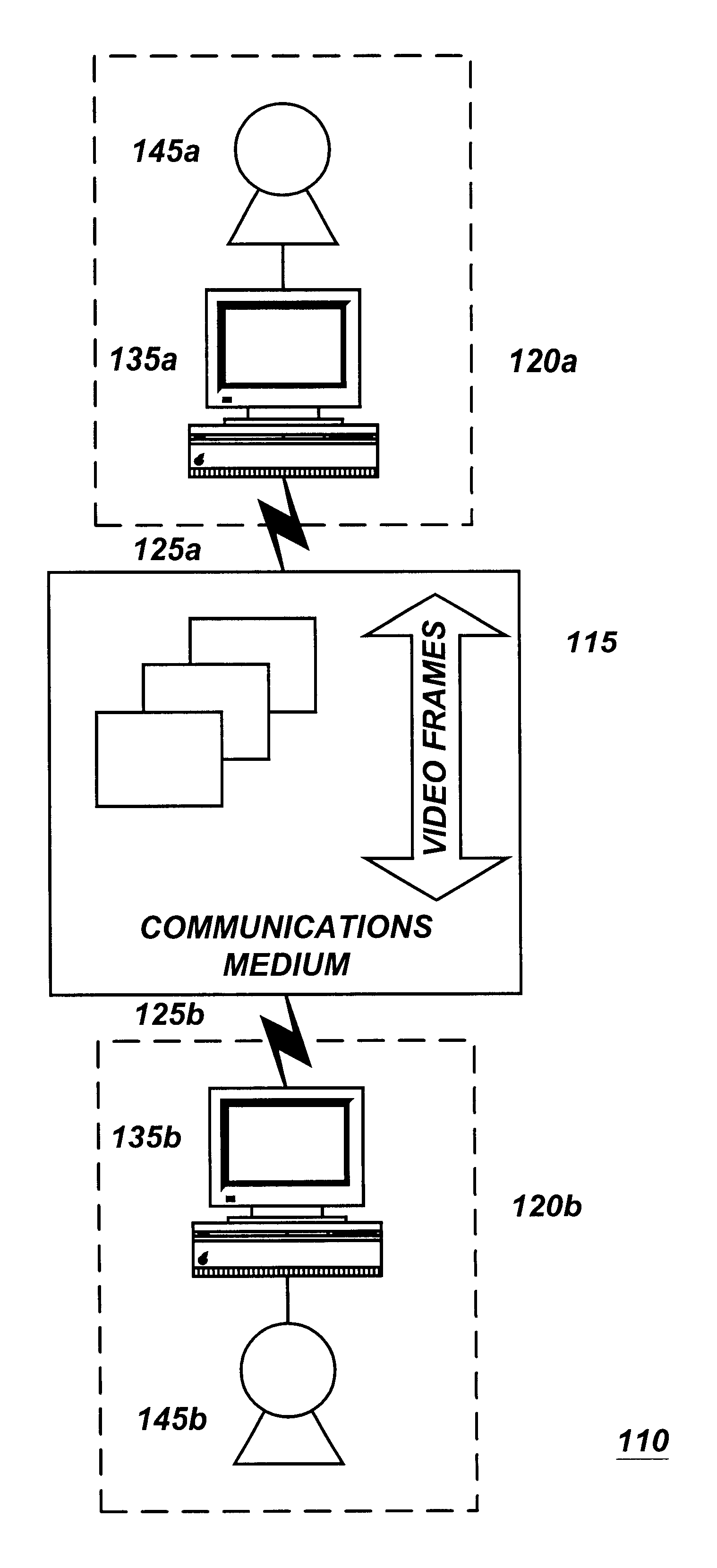
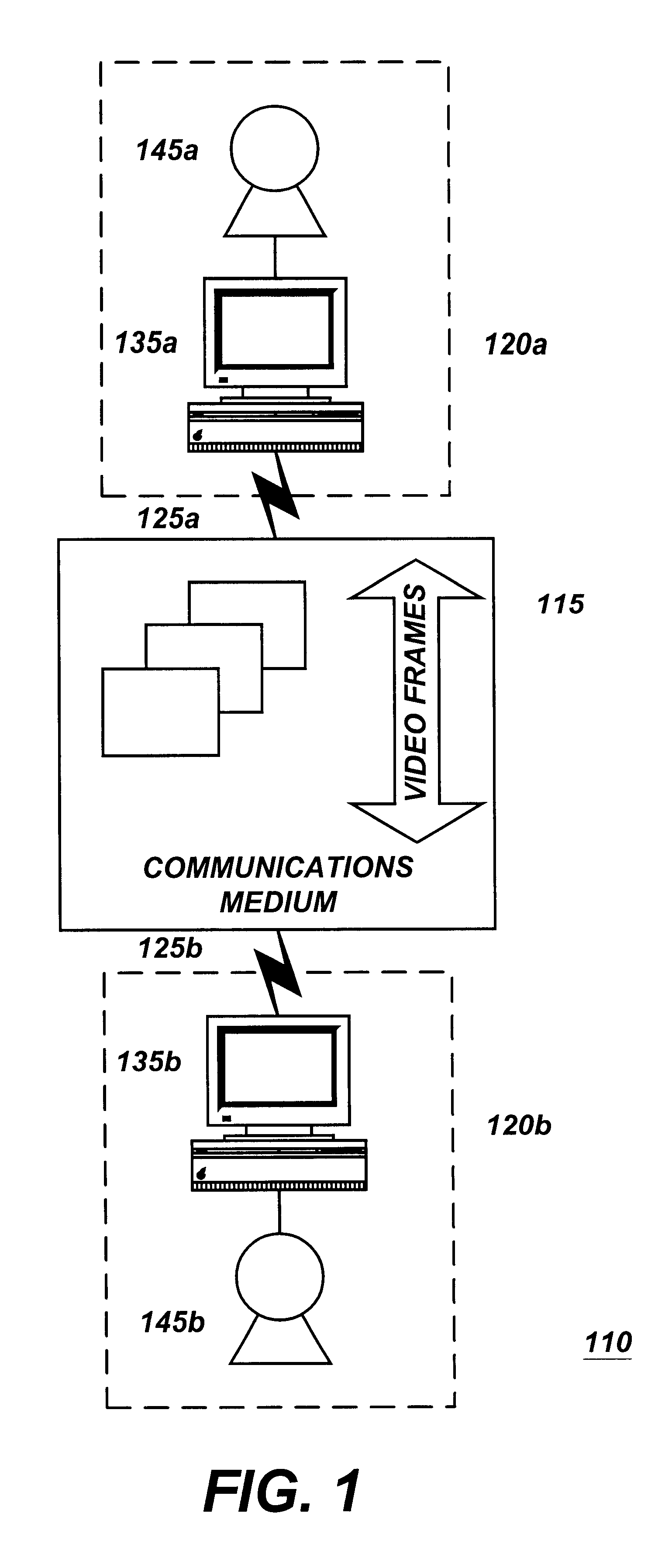
Reference will now be made in detail to several embodiments of the present invention(s), examples of which are illustrated in the accompanying drawings. It is noted that wherever practicable similar or like reference numbers may be used in the figures and may indicate similar or like functionality. One of skill in the art will readily recognize from the following discussion that alternative embodiments of the structures and methods disclosed herein may be employed without departing from the principles of the invention(s) disclosed herein. For example, the video processing system as described includes an audio processing system. For ease of discussion, the description will be for video and the principles described will be applicable to, and understood to include, audio so that references to video includes video, audio, or a combination of video and audio.

FIG. 1 is a functional block diagram of a video communication system 110 in accordance with one embodiment of the present inventio...


PUM


Abstract

The disclosure includes a video (including audio) processing system for transmission of a video frame across a network. The system includes a video input mechanism, a motion detection mechanism, and a web cam mechanism. The video input mechanism is configured to receive a first video frame and a second video frame. The motion detection mechanism is configured to compare the first video frame with the second video frame. It is also configured to generate a motion-detected signal if the comparison of the frames deviates from a threshold value. The web cam mechanism is configured to transmit the second video frame if it received the motion detection signal from the motion detection mechanism. The disclosure also includes a method for processing a selected video frame for transmission across a network. The method includes receiving a video frame, comparing it with a reference frame to determine if it deviates from a threshold value, and transmitting the video frame if it does deviate from the threshold value or discarding it if does not.

Description

1. Field of the InventionThe present invention relates to multimedia devices, and more particularly, to computer-connected video and audio devices.2. Description of Background ArtComputer connected video cameras are known, including Internet connected video cameras. Conventional Internet-connected video cameras are World Wide Web (or "Web") based video cameras. Conventional web video camera systems are configured to perform web cam functions. A web cam system includes a video transmitter and a video viewer. The video transmitter generates a video clip or video stream. The video transmitter continuously obtains (or "grabs") in rapid succession video frames and uploads (e.g., posts) them to a web server where they are saved in a file. The conventional web video camera system also includes a video viewer. The video viewer downloads the saved video frame from the file on the web server. A conventional video viewer will download saved video frames from the file on the web server at an in...

Claims


Application Information

Patent Timeline
Patent Type & Authority Patents(United States)
IPC IPC(8): H04N7/14H04N7/46
CPCH04N7/148H04N21/2187H04N19/587H04N21/6125H04N19/132H04N21/23418
Inventor STANDRIDGE, AARON D.BILLERBECK, BRYED L.BATEMAN, JOHN D.
Owner LOGITECH EURO SA
Learn More