Hydraulic brake and steering assist system

a technology of steering assist system and hydraulic brake, which is applied in the direction of braking system, braking components, transportation and packaging, etc., can solve the problems of increasing the backpressure of the pump, affecting the amount of steering gear assist applied by the hydraulic steering gear assist system, and the operator of the vehicle being able to detect the increase in steering effor

Inactive Publication Date: 2004-11-09
STEERING SOLUTIONS IP HLDG +1
View PDF8 Cites 30 Cited by
  • Summary
  • Abstract
  • Description
  • Claims
  • Application Information

AI Technical Summary

Benefits of technology

The invention further contemplates such an improved hydraulic system in which the sensing means further senses the steering assist pressure of the fluid fed to the hydraulic steering assist mechanism. At a second control pressure, preferably about the same as that associated with the brake assist system, the flow splitter operates to supply the required flow to operate the brake and steering assist mechanisms while shunting or bypassing an excess fraction of the available incoming flow from the pump around the steering and brake assist systems to another location in the system, preferably a fluid reservoir. The invention thus provides a sensing means with a double relief feature that operates to relieve both the braking and steering assist systems at preferably about the same control pressure, enabling a single flow control device to be used to control the relief of both the braking and steering assist systems. Such simplifies the overall design of the hydraulic system, requires fewer components and less space, and is less expensive to implement than a separate flow control device for each of the braking and steering assist systems.
Preferably, the diversion of fluid is achieved by choking the flow port to the brake assist system in a manner that still provides the required flow rate of fluid to both the brake and steering assist systems. Under normal operating conditions, the brake assist system requires a lesser flow rate of hydraulic than that of the steering assist system, and thus the flow to the brake assist system can be choked to provide non-uniform flow matching the different flow requirements of each system. Supplying the steering assist system with a relatively greater flow under normal operating conditions has the advantage of minimizing any noticeable increase in steering effort under a condition of hard, sudden braking where a momentary spike in the flow requirement of the braking assist system occurs. With a constant bleed of fluid to the steering assist system, the needed fluid to operate the steering assist mechanism under such sudden braking condition is already present. The choke control to provide a constant bleed of fluid to the steering assist system has the further advantage of prepositioning the sensing means closer to the relief condition, whereby the flow splitting means can react more quickly to divert a fraction of flow to the steering assist mechanism when the brake assist pressure reaches the control pressure. Such provides for a smoother transition between the various operating conditions and further minimizes any change in steering effort detected by an operator of a vehicle during such transitions.

Problems solved by technology

Because of the series arrangement, the application of the brakes and engagement of the hydraulic braking assist system can affect the flow of hydraulic fluid to the steering gear, thereby affecting the amount of assist applied to the steering gear by the hydraulic steering gear assist system.
Specifically, when a heavy braking load is applied, it causes an increase in backpressure to the pump which can exceed a threshold relief pressure (e.g., 1,500 psi) of the pump.
During this relief condition, a diminished flow of fluid is sent to the steering gear which may result in a detectable increase in steering effort by the operator of the vehicle to turn the steering wheel under extreme relief conditions.
Under normal operating conditions, the brake assist system requires a lesser flow rate of hydraulic than that of the steering assist system, and thus the flow to the brake assist system can be choked to provide non-uniform flow matching the different flow requirements of each system.

Method used


Image

  • Hydraulic brake and steering assist system
  • Hydraulic brake and steering assist system
  • Hydraulic brake and steering assist system

Examples


Embodiment Construction

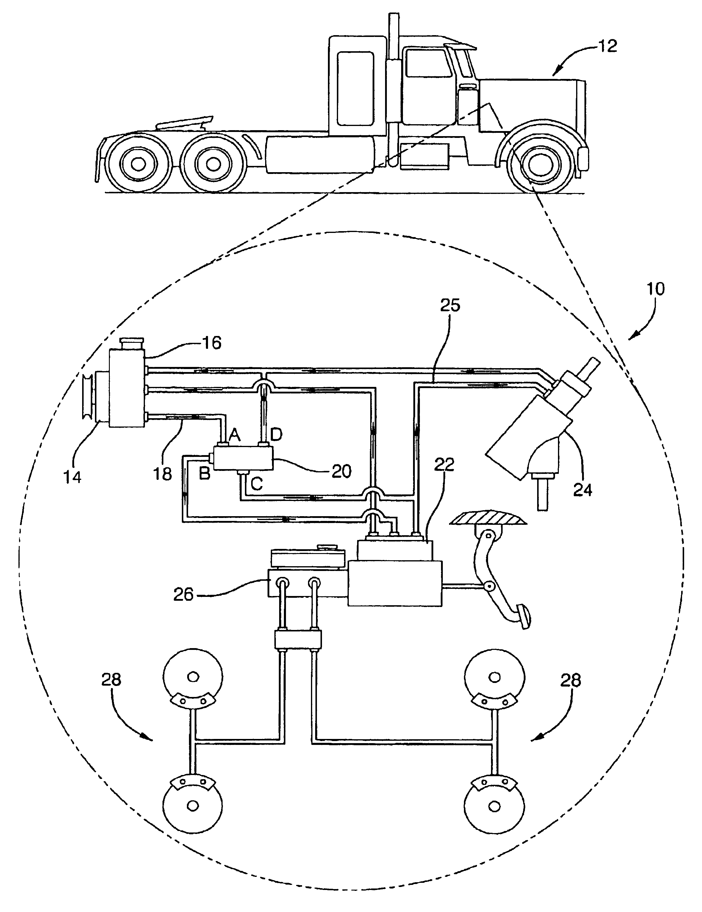
FIG. 1 shows a hydraulic system 10 for a vehicle 12 for assisting in the steering and braking of the vehicle. The hydraulic system includes a hydraulic pump 14 and reservoir 16. The reservoir may be incorporated into the pump 14, as illustrated, or may be located remote from the pump 14.

The pump 14 delivers high pressure hydraulic fluid through discharge line 18 to a flow control splitter means or device or flow splitter 20. The flow splitter 20, in turn, selectively communicates with a hydraulic braking assist system or booster device 22, a hydraulic steering gear assist system or device 24, and the reservoir 16, depending on predetermined operating conditions of the system 10, as will be explained below. The hydraulic brake assist 22 communicates with a master cylinder 26 and brakes 28 of the braking system and further with the steering assist device 24 through line 25.

The hydraulic booster device 22 is of the type well known to the art which is disposed in line between the hydrau...


PUM


Abstract

An improved hydraulically assisted braking and steering system of a vehicle having a hydraulic pump communicating with a hydraulic steering assist device and including a hydraulic brake assist device coupled in series between the pump and the steering assist device includes the provision of a flow splitter which operates to reduce the interdependence of the hydraulic brake and steering assist devices on the flow of fluid from the pump. The flow splitter communicates with the outlet of the pump and the inlet of the brake assist device and is operative when the back pressure from the brake assist device exceeds a predetermined control value to divert a fraction of the flow of fluid around the brake assist device directly to the steering assist device, thereby providing sufficient flow to operate both the brake and steering assist devices within their normal design limits, rather than having the brake assist device starve the steering assist device when under heavy load.

Description

1. Technical FieldThis invention relates to hydraulic braking and steering systems, particularly those that incorporate a hydraulically boosted assist mechanism for the braking system in line with the hydraulic steering assist system.2. Related ArtMany trucks with hydraulic braking systems incorporate hydraulic braking assist systems, rather than vacuum assist systems, particularly larger gasoline powered and diesel powered trucks. Such hydraulic braking assist systems are well known and sold commercially (e.g. the Hydro-Boost.TM. system sold by Robert Bosch Corporation). Details concerning the construction and operation of such brake assist systems are shown, for example, in U.S. Pat. Nos. 4,620,750 and 4,967,643. Generally, these hydraulic braking assist systems are connected in series between the steering gear and hydraulic pump and use flow from the pump to generate the necessary backpressure to provide brake assist as needed. The flow from the pump is constant. Because of the s...

Claims


Application Information

Patent Timeline
Patent Type & Authority Patents(United States)
IPC IPC(8): B62D5/07B60T17/02B60T13/10B60T13/16B60T17/00F15B13/02F15B13/00
CPCB60T13/163F15B13/022B62D5/07B60T17/02
Inventor DAVISON, JAMES LEROYBEAN, HENRY GEORGEPARIS, JOHNNY M.JOHNSON, MICHAEL ALAN
Owner STEERING SOLUTIONS IP HLDG
Why Eureka
Try Eureka