Intake air dehumidification system for an internal combustion engine

a technology for intake air and internal combustion engines, which is applied in the direction of domestic cooling apparatus, electrical control, machines, etc., to achieve the effect of minimizing error values and minimizing errors

Inactive Publication Date: 2004-11-16
CUMMINS INC
View PDF26 Cites 69 Cited by
  • Summary
  • Abstract
  • Description
  • Claims
  • Application Information

AI Technical Summary

Benefits of technology

The control circuit may include means for producing an error value as a difference between the target humidity value and the specific humidity value, and means for producing the number of control signals in a manner that minimizes the error value. The means for producing the number of control signals in a manner that minimizes the error value may include a controller producing a number of pulse width modulated output signals, and a driver circuit responsive to the number of pulse width modulated output signals to produce the number of control signals. The controller may control the pulse widths of the output signals as a function of the error signal to control the on-times of a corresponding number of peltier junction elements forming the peltier junction device.

Problems solved by technology

For example, in spark-ignited, natural gas engines, increased levels of specific humidity tend to slow combustion by decreasing heat release rates and also by increasing the duration of individual combustion events.

Method used


Image

  • Intake air dehumidification system for an internal combustion engine
  • Intake air dehumidification system for an internal combustion engine
  • Intake air dehumidification system for an internal combustion engine

Examples


Embodiment Construction

For the purposes of promoting an understanding of the principles of this disclosure, reference will now be made to a number of illustrative embodiments shown in the drawings and specific language will be used to describe the same. It will nevertheless be understood that no limitation of the scope of the claims appended hereto is thereby intended.

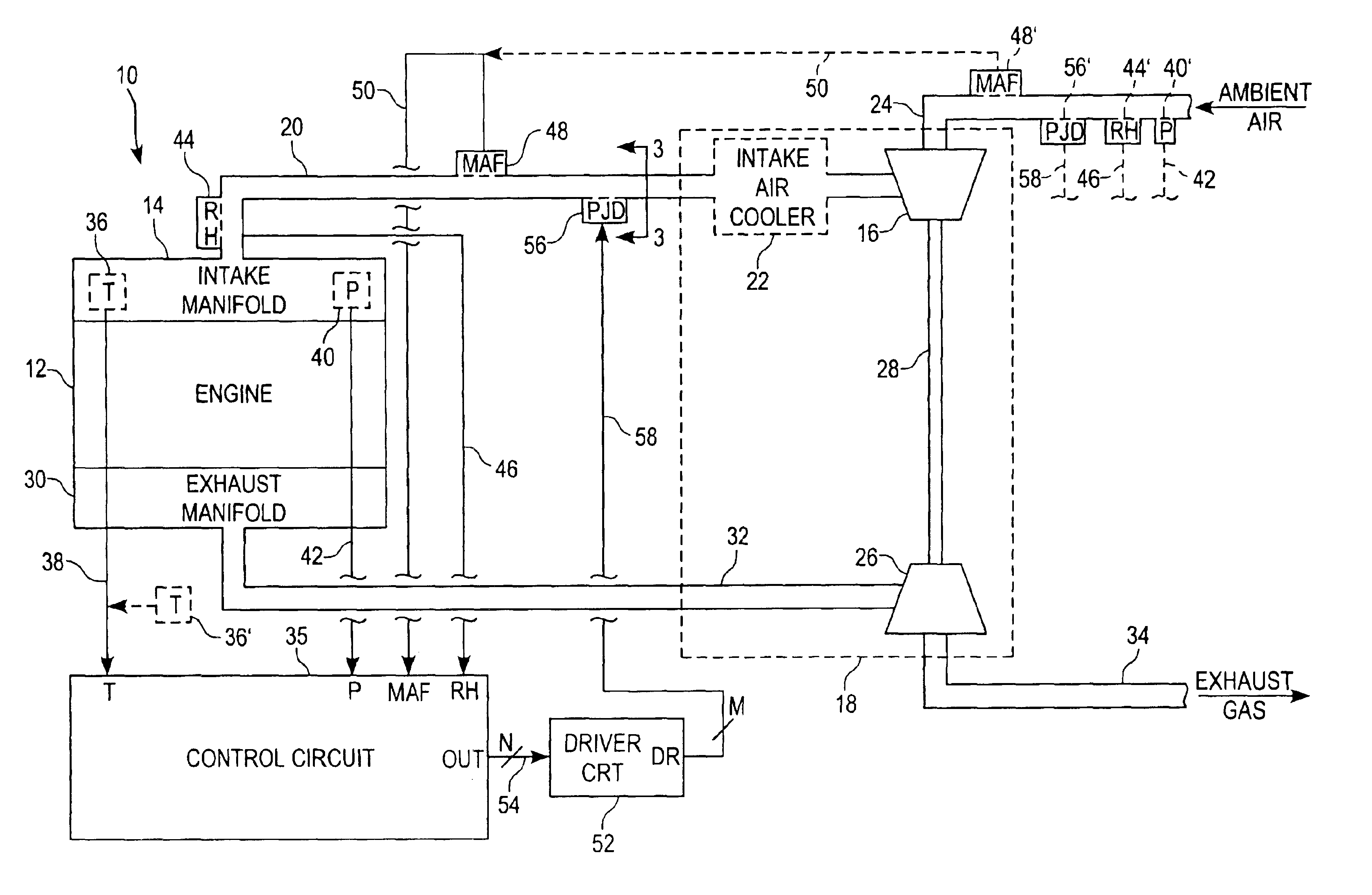
Referring now to FIG. 1, one illustrative embodiment of an intake air dehumidification system 10 for an internal combustion engine 12 is shown. System 10 includes an internal combustion engine 12 having an intake manifold 14 fluidly coupled to one end of an air intake manifold 20 having an opposite end configured to receive ambient air. An exhaust manifold 30 of engine 12 is fluidly coupled to one end of an exhaust manifold 32 having an opposite end configured to expel engine exhaust gas to ambient. In the illustrated embodiment, the opposite end of intake manifold 20 is fluidly coupled to an outlet of a turbocharger compressor 16, forming p...


PUM


Abstract

An intake air dehumidification system for an internal combustion engine includes a peltier junction device responsive to at least one control signal to cool, and therefore condense moisture from, ambient air supplied by an air intake conduit to an intake manifold of the engine. Specific humidity of the ambient air supplied to the intake manifold is determined, and a control circuit is provided to produce the at least one control signal as a function of the specific humidity to maintain the specific humidity of the ambient air supplied to the intake manifold near a target humidity value.

Description

FIELD OF THE DISCLOSUREThis disclosure relates generally to systems for controlling the humidity of intake air supplied to an internal combustion engine, and more specifically to systems for dehumidifying engine intake air.BACKGROUND OF THE DISCLOSUREDiffering levels of specific humidity in the atmosphere are known to impact the operation of internal combustion engines generally, and of spark-ignited engines in particular. For example, in spark-ignited, natural gas engines, increased levels of specific humidity tend to slow combustion by decreasing heat release rates and also by increasing the duration of individual combustion events.Heretofore, systems have been devised to compensate for such adverse humidity effects by manipulating one or more engine operating parameters. It is desirable to alternatively control humidity of the air entering the engine such that the humidity of the engine intake air is maintained near a target humidity value.SUMMARY OF THE DISCLOSUREThe present inv...

Claims


Application Information

Patent Timeline
Patent Type & Authority Patents(United States)
IPC IPC(8): F02D41/00F02B29/04F02B29/00
CPCF02B29/0468F02B29/0481F02D41/0002Y02T10/42F02D2200/0418Y02T10/146Y02T10/12Y02T10/40
Inventor PADFIELD, JON R.
Owner CUMMINS INC
Why Eureka
Try Eureka