
Vehicle wheel illumination system

a technology for vehicle wheels and illumination systems, applied in lighting and heating devices, transportation and packaging, lighting support devices, etc., can solve the problems of just becoming non-distinct, new technology wears off, etc., and achieves the effects of convenient installation and maintenance, low cost, and high illumination efficiency

Inactive Publication Date: 2004-11-16
SHARPER ALLEN
View PDF14 Cites 16 Cited by
  • Summary
  • Abstract
  • Description
  • Claims
  • Application Information

AI Technical Summary

Benefits of technology

An advantage of the present invention is that it is manufactured from inexpensive, yet durable, materials intended to provide a cost effective device that is easily installed and maintained.
is that it is manufactured from inexpensive, yet durable, materials intended to provide a cost effective device that is easily installed and maintained.
The advantages and features of the present invention will become better understood with reference to the following more detailed description and claims taken in conjunction with the accompanying drawings, in which like elements are identified with like symbols, and in which:
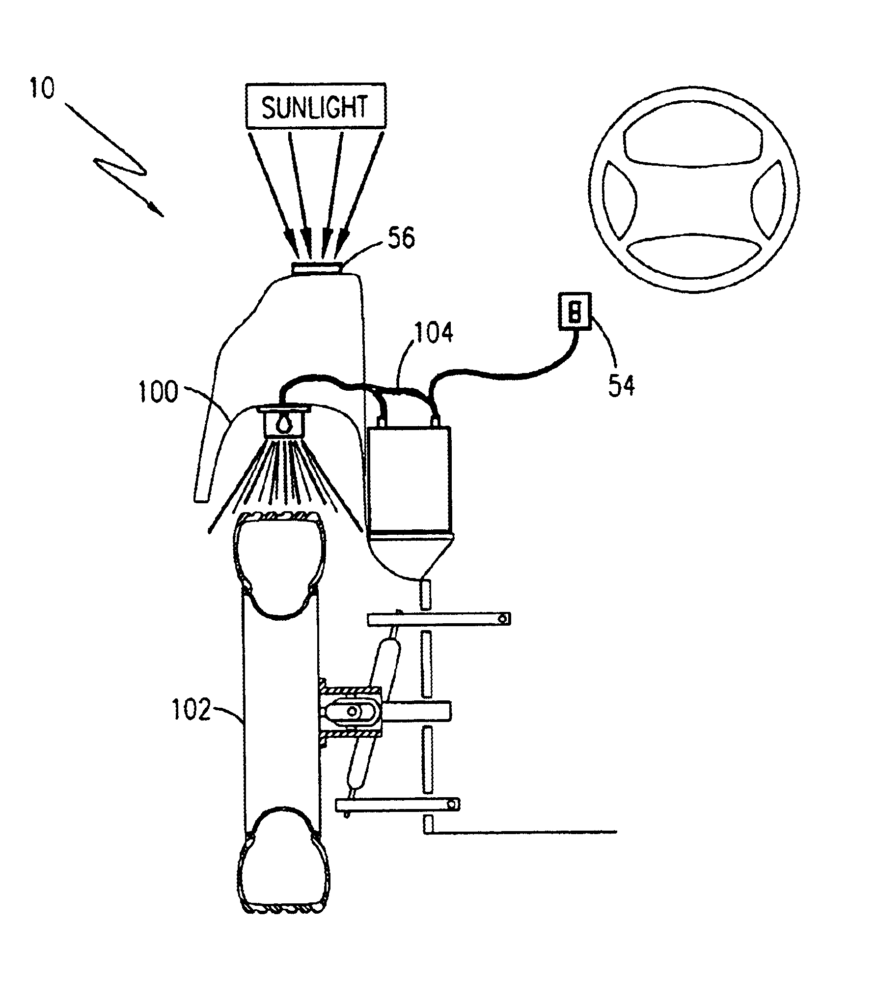
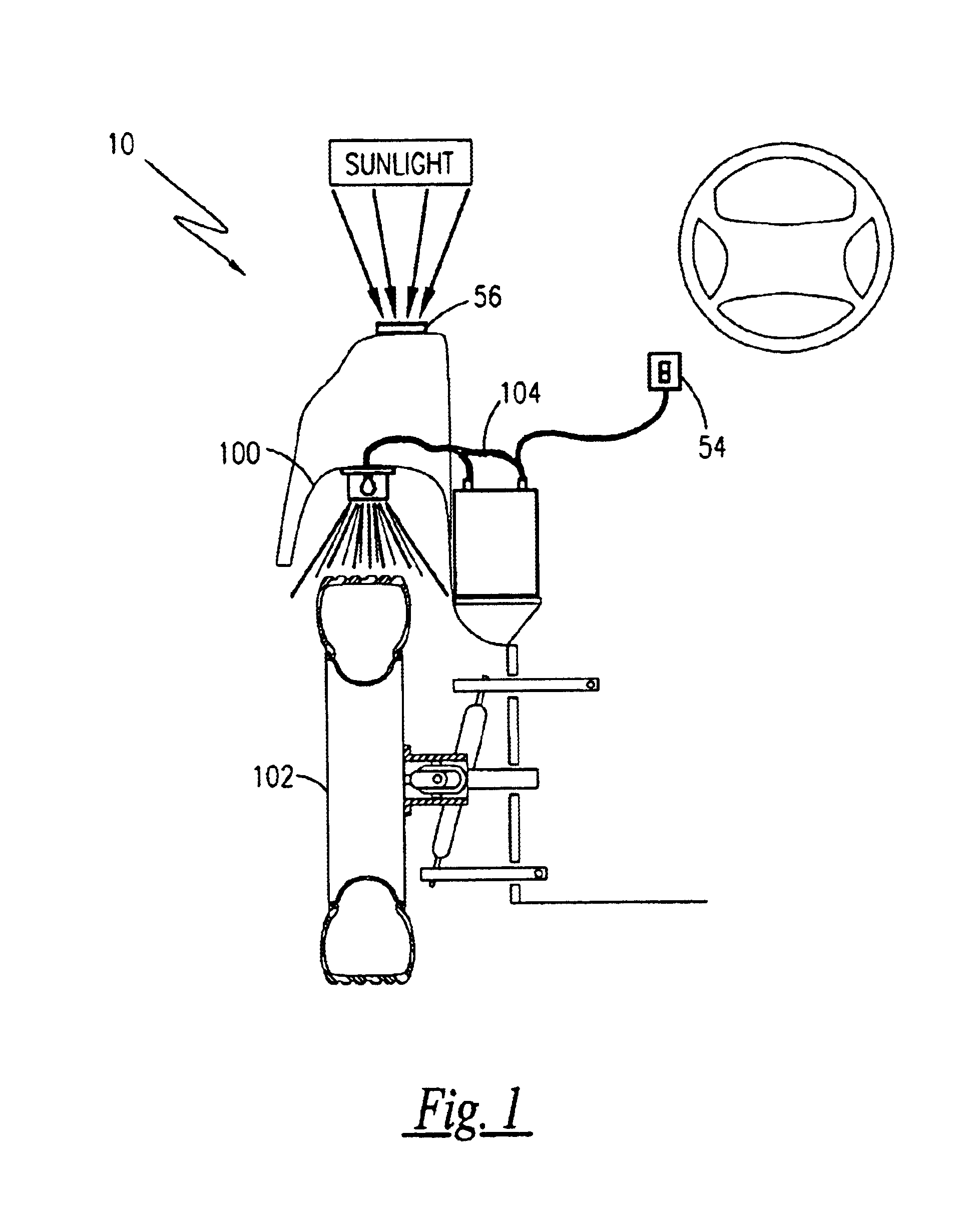
FIG. 1 is a front view and partial section of the vehicle wheel illumination system, wherein a light assembly and housing is mounted to the surface of a wheel well just above a tire, and wherein the light assembly is operably and electrically coupled with the electrical System of the automobile;
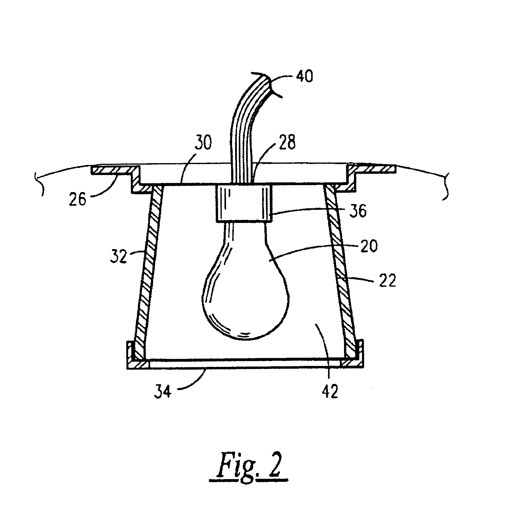
FIG. 2 is a sectional view of a light assembly and housing, wherein the housing includes a pair of mounting wings for attaching the housing to the wheel well;
FIG. 3 is a top view of the housing, illustrating the relationship of the mounting wings to the housing, and also illustrating the translucent lens;

Problems solved by technology

However, as more and people utilize these devices to draw attention, the novelty wears off, and they just become non-distinct.

Method used


Image

  • Vehicle wheel illumination system
  • Vehicle wheel illumination system
  • Vehicle wheel illumination system

Examples


Embodiment Construction

of the Figures

Referring now to FIG. 1 through FIG. 7, a vehicle wheel illumination system 10 is shown in accordance with a preferred embodiment of the present invention. The system 10 comprises four individual light assemblies 12, 14, 16 and 18 that are each separately mounted to an interior surface of each individual fender (wheel well) 100 over each individual tire 102. Each light assembly 12, 14, 16 or 18 utilizes a light source 20, envisioned to be of a low-wattage incandescent bulb 20a. Other illumination sources, such as noon black light, or colored lights 20b, may also be used separately to or in combination with in incandescent bulb 20a. The light source 20 is housed within a waterproof housing 22 with a sealed translucent lense 24 and a mounting means 26 for fastening each light assembly 12, 14, 16 or 18 to a respective fender 100. The wiring harness 28, one from each housing 22 at each tire 102, is routed through the interior of the car and is connected together in a paral...


PUM


Abstract

A vehicle wheel illumination system is a device having four separate light assemblies that are affixed above a tire and within the wheel well above the respective tire. Each light assembly includes a housing formed from a base, a wall and a cap that is removable. The base houses the electrical wiring that is coupled with a bulb stem. A bulb is inserted into the bulb stem to provide illumination. The cap includes a translucent lens through which the illuminated bulb is transmitted. The housing further includes mounting means for attaching the housing to the wheel well. The electrical wiring is further coupled to the electrical system of the automobile.

Description

1. Field of the InventionThe present invention relates generally to wheels for automotive vehicles and, more particularly, to a system of stylistically enhancement of vehicle wheels by illumination.2. Description of the Related ArtThe love affair people have with their automobiles is a well-known. Countless hours are spent cleaning, waxing, and detailing cars all around the world ever day, just so they can look their best as they drive. Many people also go to extra lengths to draw attention to their car. This is evidenced by the great popularity of custom paint schemes, custom wheels, and even special neon lights located on the bottom of the car or around the license plate. However, as more and people utilize these devices to draw attention, the novelty wears off, and they just become non-distinct. Accordingly, there exists a continual need for devices that provide a custom look for motor vehicles and which provide an attention-gathering factor.A search of the prior art did not disc...

Claims


Application Information

Patent Timeline
Patent Type & Authority Patents(United States)
IPC IPC(8): B60Q1/32F21V33/00
CPCB60Q1/326
Inventor SHARPER, ALLEN
Owner SHARPER ALLEN
Learn More