
Surgical fixation and retraction system

a surgical fixation and retraction technology, applied in the field of surgical fixation and retraction system, can solve the problems of restraining limbs and digits, difficult to add or change equipment in an operating room without compromising, and the change of the conventional surgical fixation and retraction device is slow,

Inactive Publication Date: 2004-11-30
CANICA DESIGNE
View PDF32 Cites 59 Cited by
  • Summary
  • Abstract
  • Description
  • Claims
  • Application Information

AI Technical Summary

Problems solved by technology

As a result, conventional surgical fixation and retraction devices have changed slowly and suffer from a number of shortcomings.
Restraining limbs and digits provides a particular challenge for medical personnel.
This presents problems because it is difficult to add or change equipment in an operating room without compromising the sterile environment.
As a result, surgical procedures can be delayed while additional sterile equipment is introduced to the operating facility.
Another problematic shortcoming of existing fixation systems is their reliance on threaded or incremental adjusters.
Threaded adjusters are frequently too slow for mid-procedure adjustment.
Incremental adjusters are faster but often exert too little or too much retraction in detent positions.
As a result, procedure errors can occur because of misunderstood verbal communication between the surgeon and the assistant.
Users of this traditional fabric encounter problems of poor fluid transmission control and virtually no containment of fluids.
However, new problems are associated with use of the Goretex.TM. drape.
Holes in the drape resulting from the pincer style towel clips destroy the desirable properties of the membrane.
It is also undesirable to puncture such drape material with sutures.
However, double faced adhesive tapes lack the ability to adhere to the drapes effectively, particularly when attaching drapes to skin.
This problem has led to somewhat extreme procedures such as scrubbing the patent to improve adhesion.
Thus, current fastening methods are inefficient and unreliable, and a need exists for a method and system for securing a surgical drape to a skin surface without puncturing the surgical drape.
Use of rare-earth magnets in medical applications is challenging.
Normal magnet plating will not withstand repeated cleaning cycles, and encapsulation degrades magnetic performance.
In a surgical environment, radiating magnet flux attracts all ferromagnetic materials, which can be undesirable.

Method used


Image

  • Surgical fixation and retraction system
  • Surgical fixation and retraction system
  • Surgical fixation and retraction system

Examples


Embodiment Construction

Overview

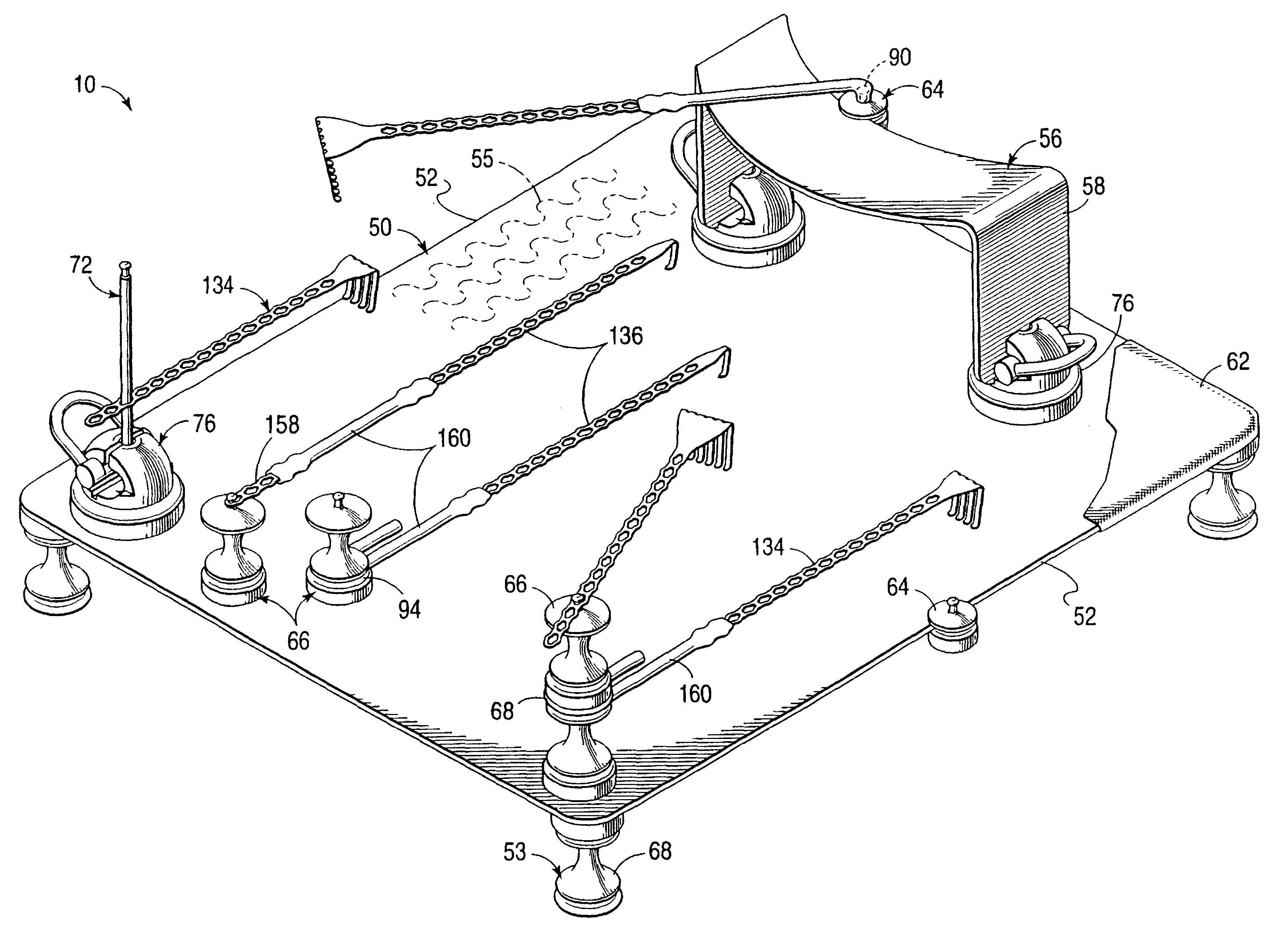
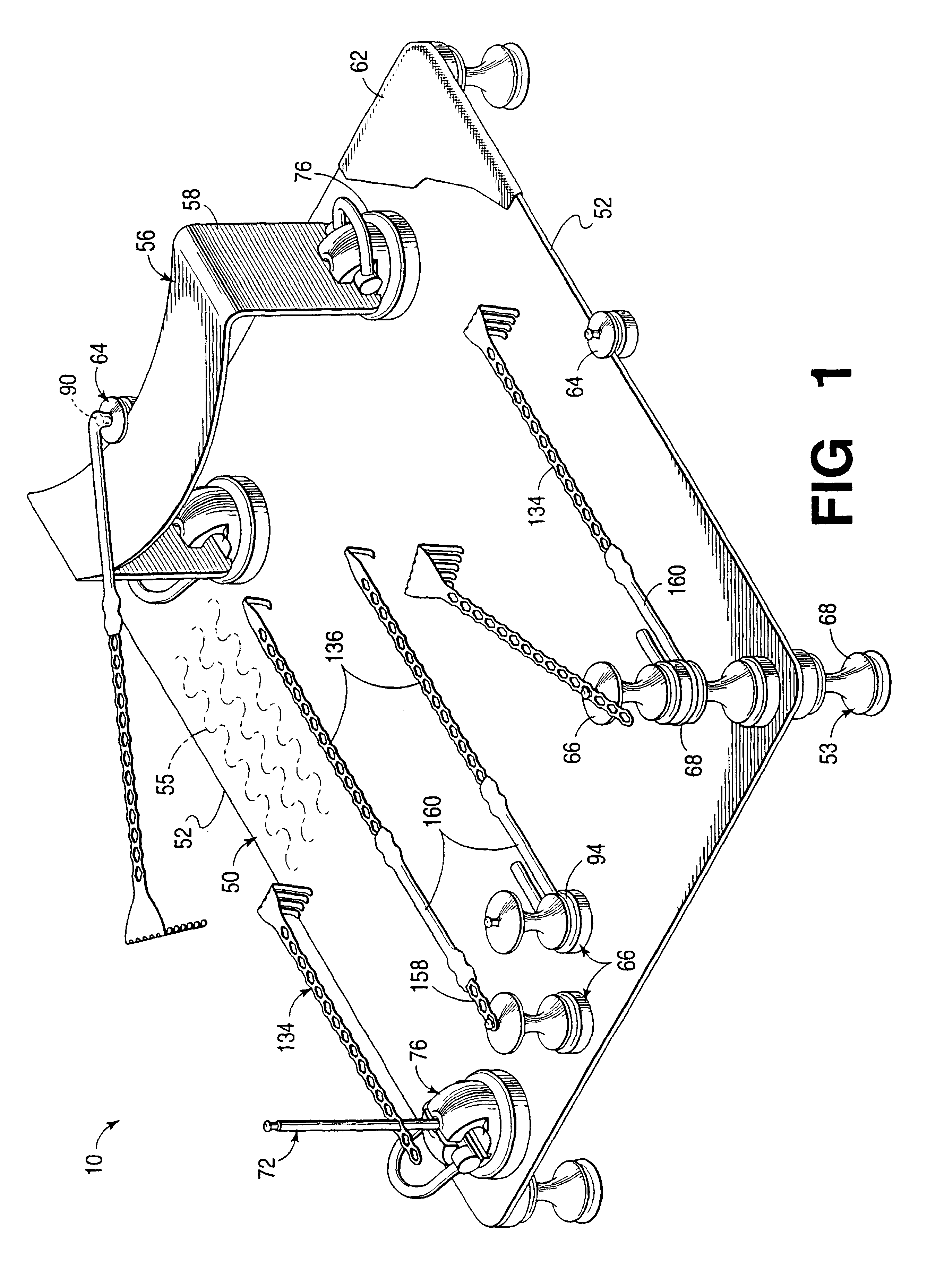
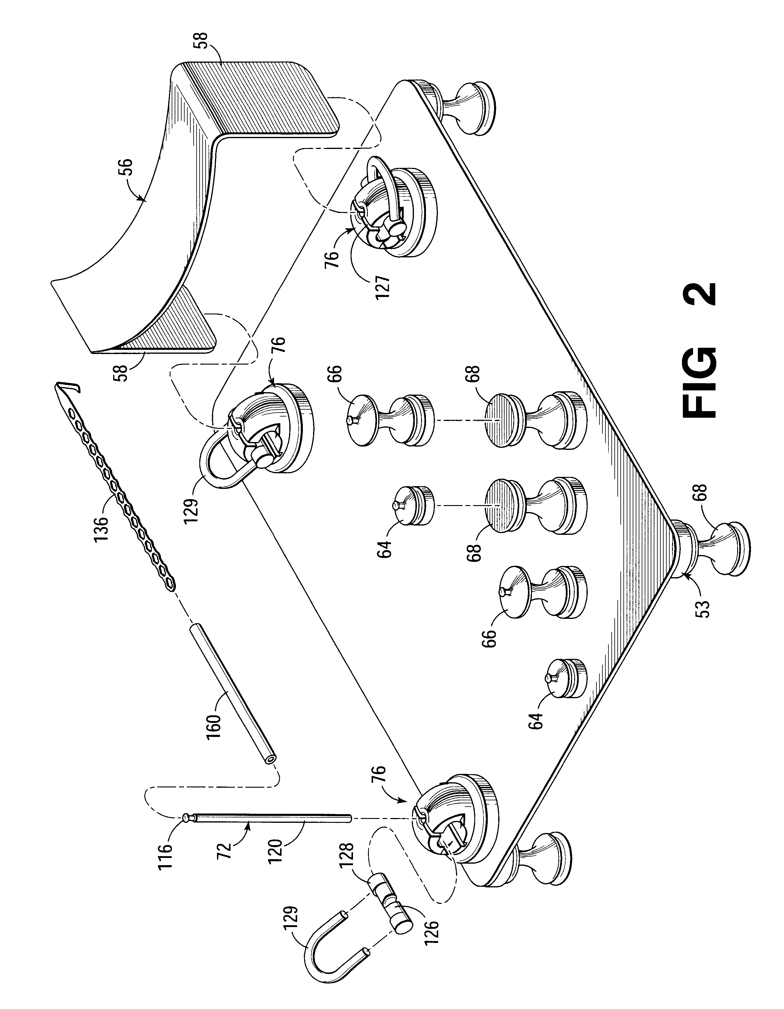
This fixation and retraction system 10 may be utilized during a surgical procedure to stabilize, immobilize, or retract structures such as, but not limited to, flesh, bone, feet, legs, arms, hands, digits, surgical drapes, and other surgical equipment. The system 10 generally includes table components, fixation components, retraction components, and dynamic components. Various components are used for coupling a magnet to anatomical members or other surgical theater devices such as surgical drapes. FIG. 1 illustrates possible combinations of the components of the system to form a variety of magnetic and mechanical structures. FIG. 2 shows discreet components as an exploded perspective view. FIG. 3 shows various components of the system, as used during a surgical procedure of the hand. FIGS. 4-23 illustrate individual components of the system in more detail, while FIGS. 24-26 show additional combinations. FIGS. 27-30 show alternative embodiments of the system for use in securi...


PUM


Abstract

A fixation and retraction system utilizing base components to which shielded magnet components attach in order to locate movable fixation and retraction components or other operating theater devices, such as surgical drapes. Use of rare earth magnets permits system components to be attached quickly, easily and securely in almost an infinite number of configurations.

Description

1. Field of the InventionThis invention relates to systems and methods for fixation or immobilization and retraction of various anatomical and other structures during surgery, including, for example, surgical fixation and retraction of flesh, bone, feet, legs, arms, hands, digits, surgical drapes, and other surgical equipment.2. Prior ArtAlthough elements of many new technologies have been transferred to medicine from their original fields, this has generally not happened in the area of basic surgical instruments, even though surgery still largely depends on the skill of an individual surgeon using these tools. Recent research and development activity in medical equipment has been more focused on expensive procedure sets, diagnostic tools, and life-support systems. As a result, conventional surgical fixation and retraction devices have changed slowly and suffer from a number of shortcomings.(a) RetractionSurgical retractors are used to provide medical personnel with the ability to h...

Claims


Application Information

Patent Timeline
Patent Type & Authority Patents(United States)
IPC IPC(8): A61B17/02A61B19/02A61B19/00
CPCA61B17/02A61B17/0293A61B2017/0287A61B19/0271A61B19/0256A61B50/20A61B50/33
Inventor BELL, MICHAEL S. G.LEE, LEONARD G.O'MALLEY, MICHAEL T.MAXWELL, TIMOTHY J.
Owner CANICA DESIGNE
Learn More