
Alignment device

a technology of aligning device and guide, which is applied in the direction of photomechanical equipment, instruments, printing, etc., can solve the problems of limited guide accuracy, limited final positioning accuracy, and limited final positioning accuracy

Inactive Publication Date: 2004-11-30
EIJI SHAMOTO
View PDF11 Cites 11 Cited by
  • Summary
  • Abstract
  • Description
  • Claims
  • Application Information

AI Technical Summary

Benefits of technology

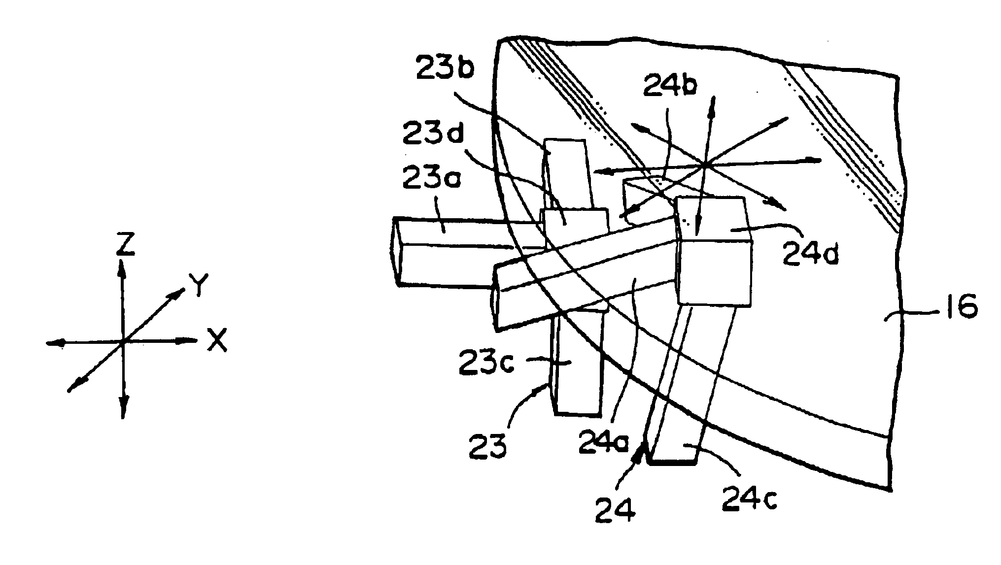
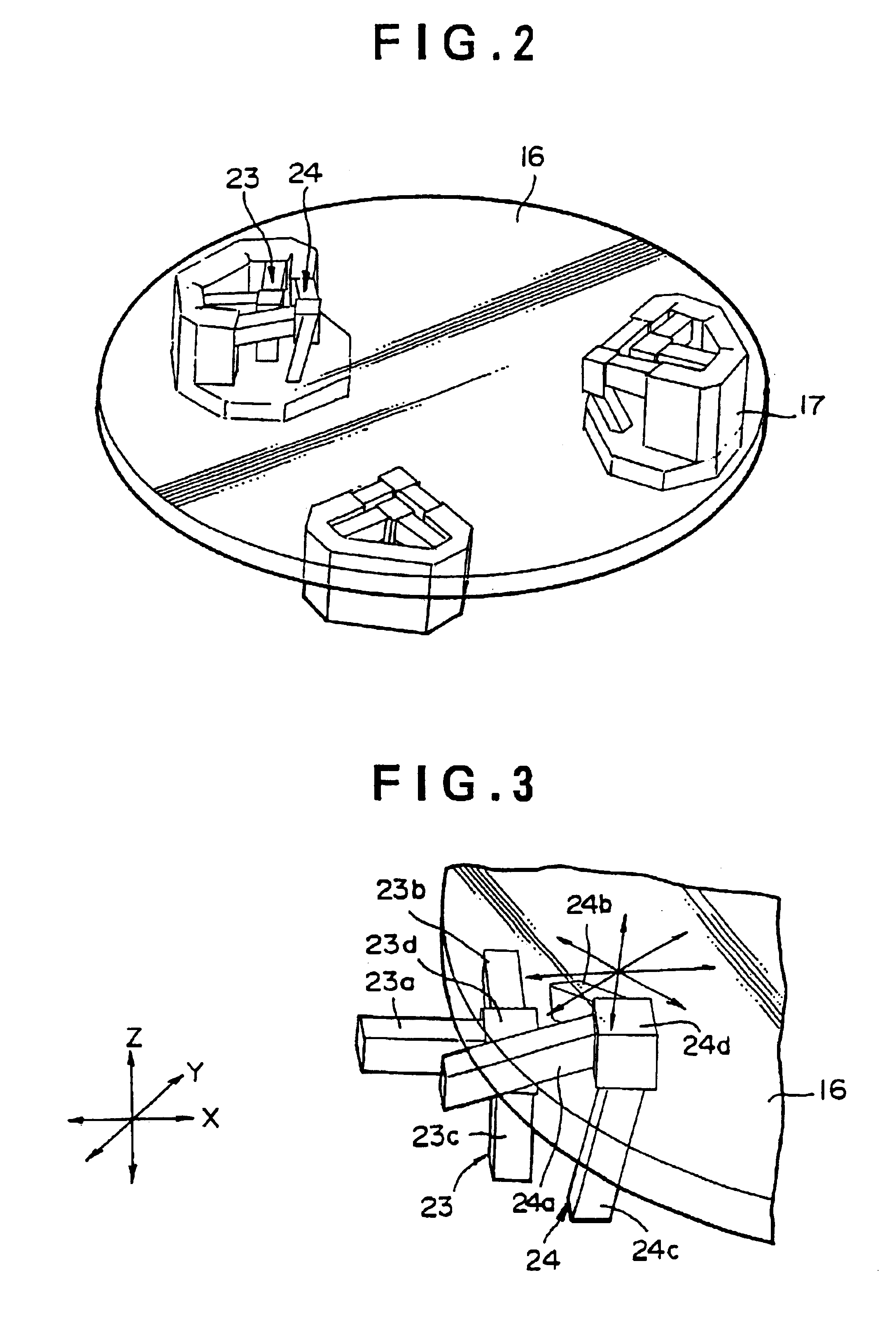
Namely, in the above-described alignment device, in each piezoelectric actuator of each movable support means, the support block is brought into contact with or separated from the movable table by the expansion and contraction operation (hereinafter, merely referred to as expansion operation in this specification) of the third piezoelectric element, and the support block is moved in the two-dimensional direction, that is the horizontal direction, by the expansion operations of the first and second piezoelectric elements, and accompanying with the movement, the third piezoelectric element is swung. The third piezoelectric element is repeatedly brought into contact with and separated from the movable table via the support block, accompanying therewith the swing operation is repeated, and by the condition where this operation is performed for each piezoelectric actuator of the pair of piezoelectric actuators alternately, two third piezoelectric elements operate as if they were in a walking motion relative to the movable table, and this motion is exhibited as the walking operation. This walking operation is a relative operation to the movable table, and actually, the movable table side is moved by driving the plurality of movable support means. By controlling the drive of the plurality of movable support means, the movable table can be adjusted in position in a single plane simultaneously in X-axis and Y-axis directions (horizontal direction) and .theta. direction (rotational direction), and besides, the position of the rotational center can also be controlled arbitrarily, and therefore, the object can be moved to a target position with a high accuracy at a time by the specified movable support means using piezoelectric elements.
In this positioning, because basically it is not necessary to have a mechanical guide structure, the positioning accuracy is not limited originating from the mechanical guide structure. Further, because the movable table can be driven in a single plane simultaneously in X-axis, Y-axis and .theta. directions by the drive of the plurality of movable support means, the distance up to the positioning surface on the movable table or on the object held on the movable table may be small from the viewpoint of this drive system due to the plurality of movable support means, and therefore, there does not occur a problem of amplification of an control error in the drive of the positioning surface ascribed to this distance, which has occurred in a case where the distance from a drive surface to a positioning surface becomes relatively large such as a case of a conventional device. Therefore, a high accuracy for positioning can be ensured. Namely, since an efficient and high-accuracy positioning can be performed at a time by the plurality of movable support means without using a mechanical guide structure, an error ascribed to the drive for positioning hardly occurs, and a high-accuracy positioning becomes possible. Further, since the drive plane in X-axis, Y-axis and .theta. directions by the plurality of movable support means becomes substantially a single plane, the drive efficiency for positioning is good. Furthermore, because the plurality of movable support means form one set of positioning means disposed substantially on a single plane, the alignment device can be reduced in size particularly in the vertical direction, as compared with a case where position adjusting tables for the respective axes directions and the rotational direction are stacked such as a case of a conventional device.
Further, since piezoelectric elements capable of controlling the expansion amounts with a high accuracy are used for the control of the movement of the movable table by the plurality of movable support means, namely, since piezoelectric elements each having an extremely high resolution are used (at present, although the resolution of a piezoelectric element itself is less than an angstrom level, the resolution of a measurement / control system including a piezoelectric element and various equipment is about 12 nm, and it is possible to further improve the resolution to a level less than 5 nm by changing the control structure), a significantly high-accuracy positioning becomes possible. Further, even if the size of an object to be positioned becomes large, because the respective movable support means can be disposed at positions corresponding to the radially outer portions of the object, the resolution particularly in .theta. direction can be maintained to be high.
The above-described alignment device according to the present invention may be constructed so that the coarse positioning of the object is carried out by the walking operation, and the precise positioning of the object is carried out by the expansion operations of the respective piezoelectric elements at a condition where the walking operation is stopped. Since the amount of expansion of each piezoelectric element can be controlled at a significantly high accuracy although the amount itself cannot be increased so much, it is possible to perform the positioning at a submicron level, which has been impossible in the conventional technology, and further at a nanometer level, by such a high-accuracy adjustment after the coarse adjustment due to the walking operation.
It is preferred to perform the above-described precise positioning of the object within a range of one step of the walking operation. By this, the high-accuracy fine adjustment utilizing the expansion operations themselves of the piezoelectric elements after the above-described coarse adjustment can be carried out more surely. Further, it is preferred that the swing position of the third piezoelectric element due to the expansion operations of the first and second piezoelectric elements is reset to a center position in a range of one step of the walking operation before the precise positioning of the object. By this, the high-accuracy fine adjustment utilizing the expansion operations themselves of the piezoelectric elements after the above-described coarse adjustment can be carried out in an arbitrary direction.

Problems solved by technology

In such a conventional alignment device, however, because the adjustment is carried out in order with respect to the respective directions (for example, X-axis and Y-axis directions and .theta. direction), even if a relatively high-accuracy positioning becomes possible only in one direction, there is a case where the positioning accuracy in the direction already adjusted goes wrong when the positioning in the other directions is performed, and consequently, the final positioning accuracy is limited.
Further, since usually a mechanical guide is used for positioning, there is a limit in the accuracy of the guide, and also from this point of view, the final positioning accuracy is limited.
More concretely, in a conventional alignment device, the possible positioning accuracy is an accuracy which cannot expect a submicron-level positioning, and therefore, a several-ten nanometer-level or several nanometer-level positioning is impossible by the conventional possible positioning accuracy.
Further, as aforementioned, since a conventional alignment device is constructed by stacking tables adjustable in position in X-axis and Y-axis directions and .theta. direction, when an axis A except an uppermost axis is adjusted, an axis stacked above the axis A must be driven, and therefore, the efficiency of the drive and control for positioning is not good.
Moreover, when the device is constructed by stacking tables adjustable in position in X-axis and Y-axis directions and .theta. direction, the thickness (the size in the vertical direction) of the entire alignment device increases, and therefore, an apparatus incorporating this alignment device, for example, a mounting apparatus or an exposure apparatus, inevitably becomes large-sized.
Further, because the distance from a guide to an uppermost positioning surface becomes large, an error of the guide is amplified, and this may give a bad influence to the positioning accuracy.

Method used


Image

  • Alignment device
  • Alignment device
  • Alignment device

Examples


Embodiment Construction

Hereinafter, desirable embodiments of the present invention will be explained referring to figures.

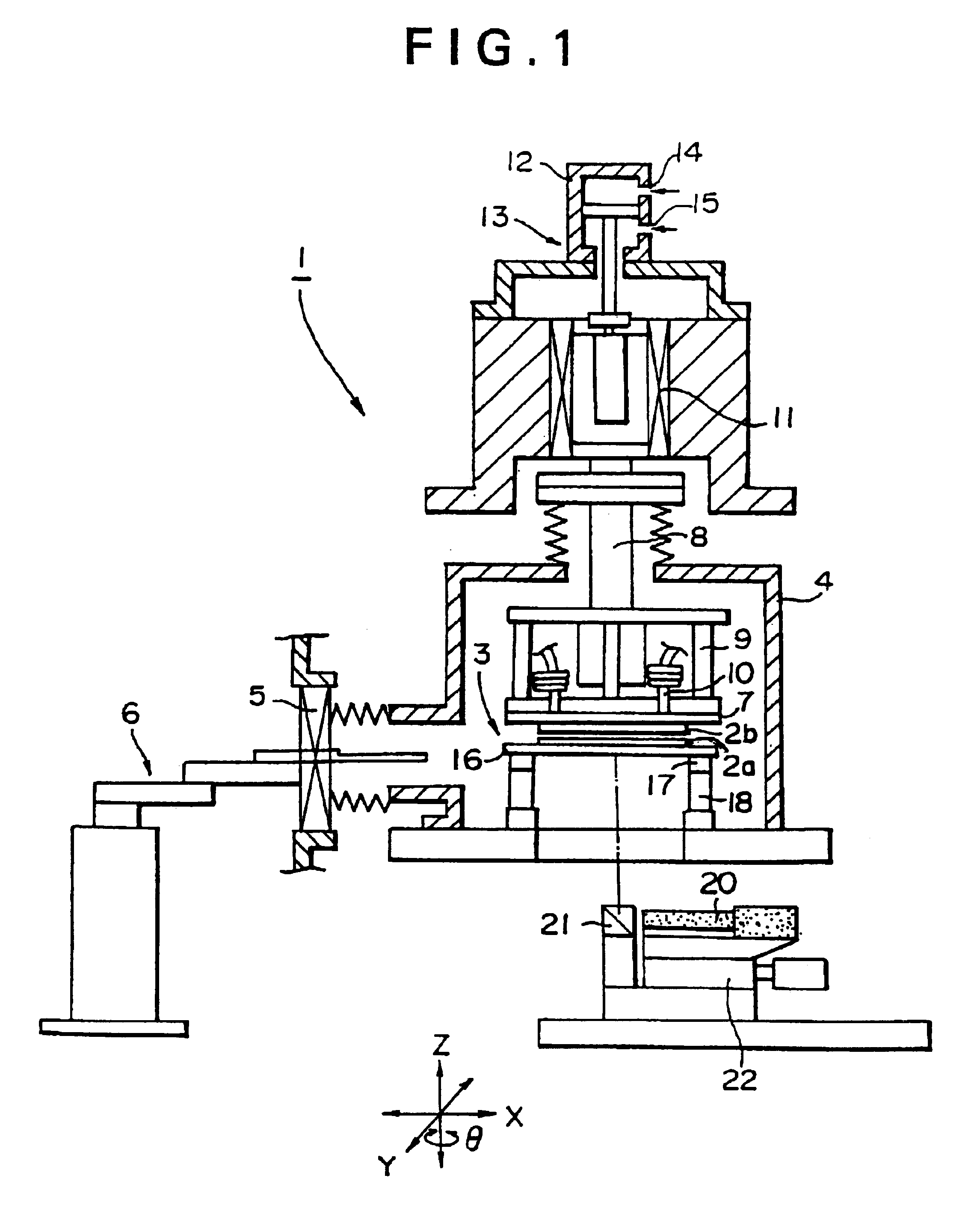
FIG. 1 shows a mounting apparatus for bonding wafers to each other which is incorporated with an alignment device according to an embodiment of the present invention. Mounting apparatus 1 bonds a wafer 2a and a wafer 2b prepared as object to be bonded to each other, and in this embodiment, an alignment device 3 according to the present invention is incorporated for positioning the wafer 2a provided as an object to be positioned.

Although the bonding of wafer 2a and wafer 2b is carried out in a bonding chamber 4 in this embodiment, the chamber 4 may be provided as needed. In this embodiment, a gate 5 capable of being opened / closed is provided to bonding chamber 4, and at a condition where the gate 5 is opened, wafers 2a and 2b as objects to be bonded to each other are introduced into the bonding chamber 4 by a robot 6 provided as a conveying means.

In the bonding part for bonding the obje...


PUM

PropertyMeasurementUnit
piezoelectricaaaaaaaaaa
thicknessaaaaaaaaaa
distanceaaaaaaaaaa

Abstract

An alignment device comprising a movable table, a plurality of movable support means for movably supporting the movable table, means for reading a recognition mark, and a control means for controlling the drive of the movable support means based on information from the recognition means, wherein each movable support means comprises means having a pair of support blocks each provided to be able to contact / separate with / from the movable table and a pair of piezoelectric actuators each provided with expansible first, second and third piezoelectric elements connected to a support block and extending in each direction, and being capable of walking operation relative to the movable table by the operations of the respective piezoelectric actuators. An alignment accuracy up to a nanometer level can be attained, and the alignment device itself and therefore the entire apparatus incorporating the alignment device can be significantly reduced in thickness and size.

Description

The present invention relates to an alignment device which can position an object to be positioned at a high accuracy within a target accuracy, and specifically to a device suitable for alignment in an apparatus such as a mounting apparatus or an exposure apparatus for wafers, etc.BACKGROUND ART OF THE INVENTIONFor example, in a mounting apparatus for bonding wafers to each other, an aligner for positioning a wafer at a predetermined position in order to processing the wafer or mounting a chip or other parts on the wafer, or an exposure apparatus for performing a predetermined exposure on a wafer, it is necessary to position the wafer at a predetermined position with a high accuracy. As a conventional alignment device used for such positioning of an object to be positioned, for example, used is a device wherein tables adjustable in position in X-axis and Y-axis directions (a horizontal direction) and .theta. direction (a rotational direction) are stacked and as needed a table or a h...

Claims


Application Information

Patent Timeline
Patent Type & Authority Patents(United States)
IPC IPC(8): B23Q1/34B23Q1/26G03F7/20H01L21/68H01L21/67H01L21/00G01B11/00G01B21/00H01L21/027
CPCB23Q1/34G03F7/707H01L21/68H01L21/67259H01L21/67294G03F7/70708B82Y30/00
Inventor YAMAUCHI, AKIRAARAI, YOSHIYUKIINAKA, CHISASHAMOTO, EIJIMORIWAKI, TOSHIMICHI
Owner EIJI SHAMOTO
Learn More