
Rack mountable computer component power distribution unit and method

a computer component and power distribution unit technology, applied in the direction of insulated conductors, cable connections, coupling devices, etc., can solve the problems of waste of space between the back plane space and the fan exhaust plenum, high cost of individual fans mounted in each component, and time-consuming replacement, etc., to facilitate the rearward re-direction of air flow

Inactive Publication Date: 2004-12-28
BOXX TECH LLC
View PDF48 Cites 58 Cited by
  • Summary
  • Abstract
  • Description
  • Claims
  • Application Information

AI Technical Summary

Benefits of technology

"The present invention is a rack mounted system that includes a rack housing with a plurality of vertical bays for accommodating computer components. The rack housing has a bottom opening for air flow and a fan / LAN tray that can be installed to facilitate air flow. The fan / LAN tray includes a plurality of fans and LAN connector ports for connecting to the switch module. The system also includes casters for easy portability and can be floor mounted. The fan / LAN tray can be removed independently for maintenance. The system also includes guides for easy installation and a locking mechanism for securing the fan / LAN tray. The technical effects of the invention include a compact, closely spaced computer component configuration, improved air flow, and easy portability and maintenance of the system."

Problems solved by technology

The individual fans mounted in each component are expensive, and time-consuming to replace in case of malfunctions.
Also, the back plane space and fan exhaust plenum chamber are wasted space in that they occupy spaces which could otherwise be filled with computer components.
Such an operation is time consuming, and therefore expensive since highly trained personnel are required to do such an installation.
This, too, is time consuming and expensive.
However, due to the cabling requirements for such a large number of computer components mounted in a single rack, it is difficult to install the components within the rack due to the cabling requirements and still have a very densely packed configuration.

Method used


Image

  • Rack mountable computer component power distribution unit and method
  • Rack mountable computer component power distribution unit and method
  • Rack mountable computer component power distribution unit and method

Examples


Embodiment Construction

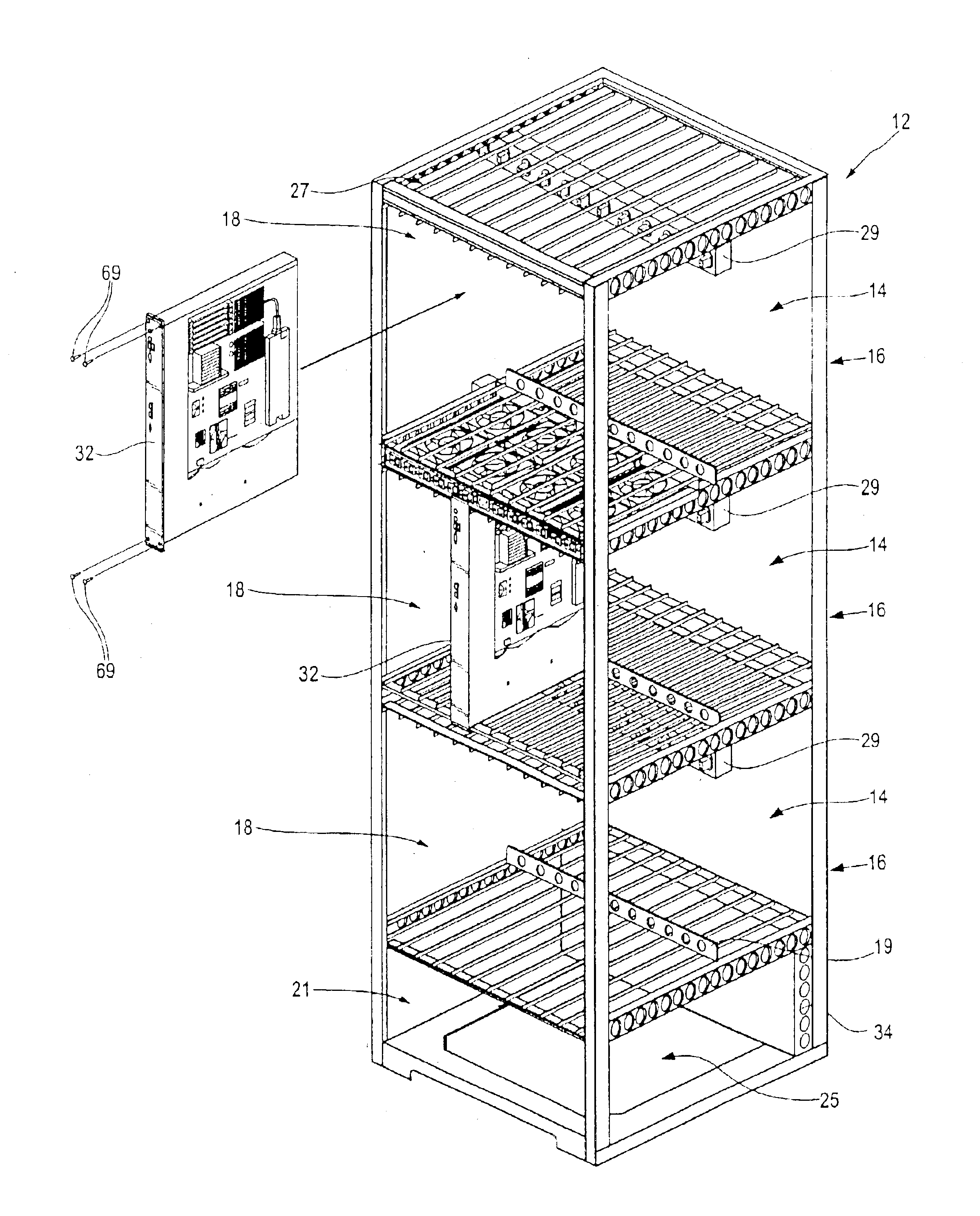
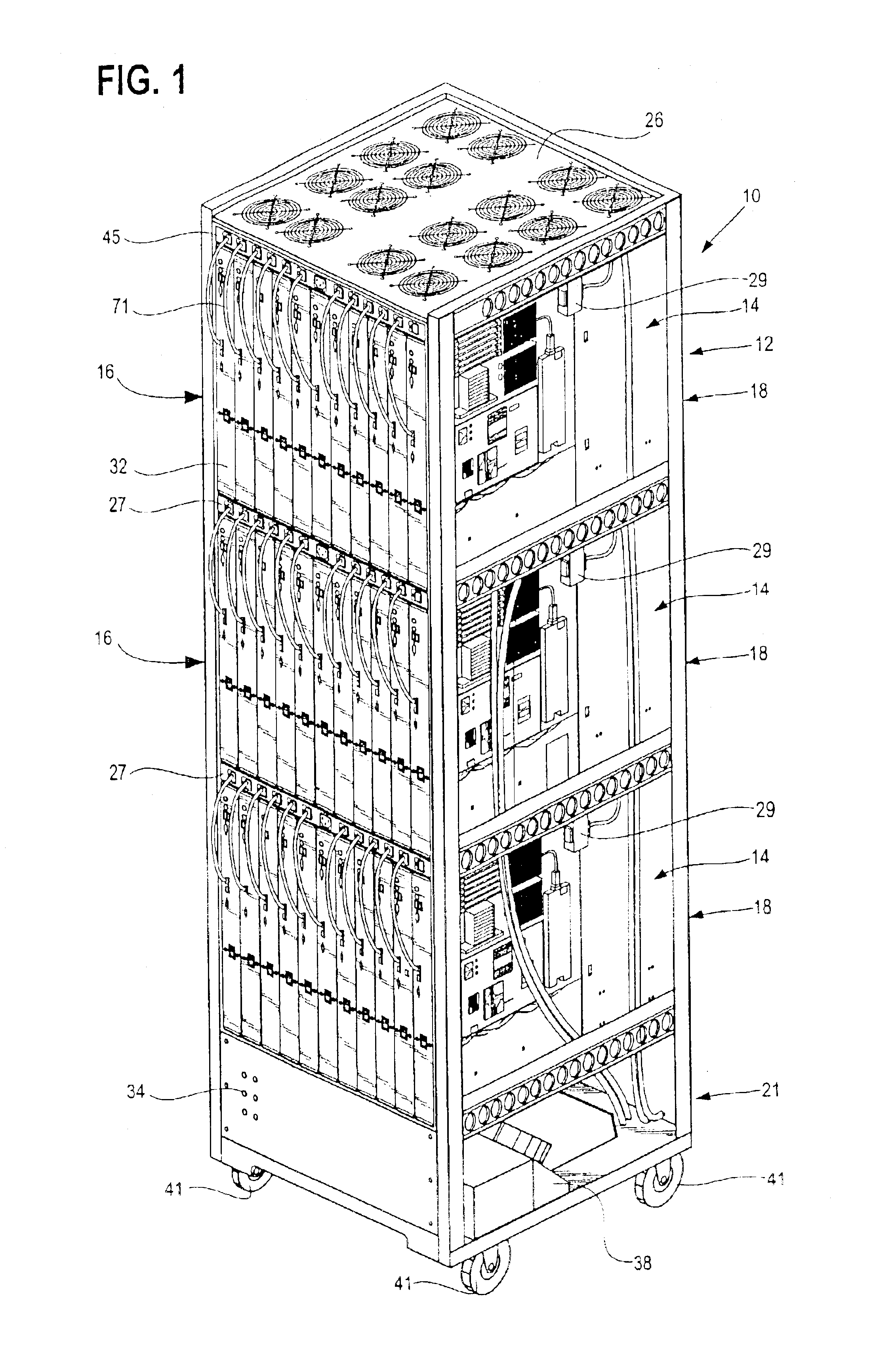
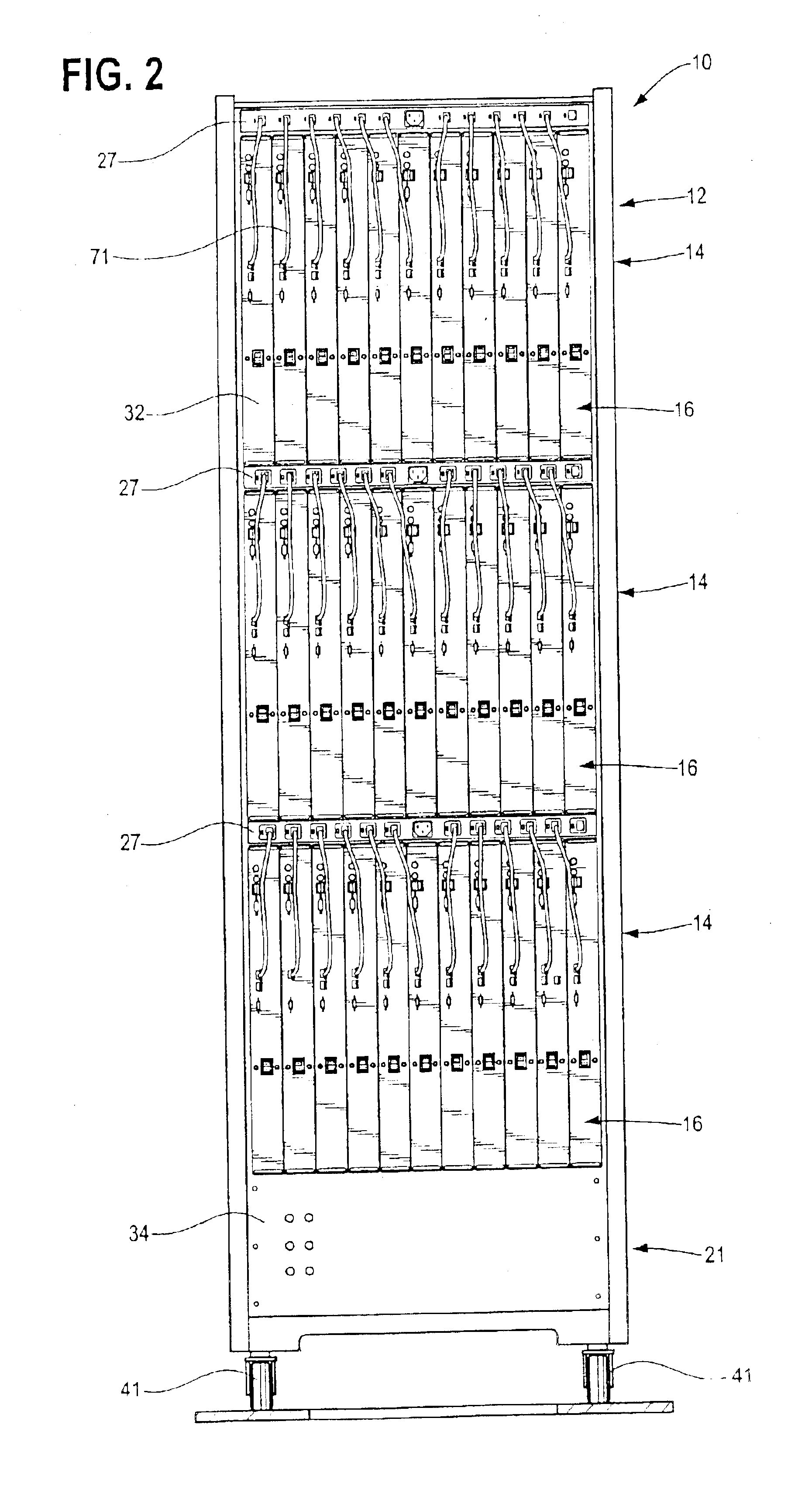
According to the disclosed embodiments of the invention, there is provided a method of supplying electrical power to a series of upright computer blades mounted side-by-side in a closely spaced configuration, including extending an elongated power distribution unit transversely to the upright blades, and electrically interconnecting the upright blades with a series of electrical connectors arranged side-by-side on one side of the distribution unit. In one embodiment of the invention, a second series of electrical connectors are arranged side-by-side on the opposite side of the body of the power distribution unit.

According to other embodiments of the invention, each one of the computer component blades has a similar cut out portion, and the body of the power distribution unit has a complementary cross sectional shape received by the cut-away portions of the blades to provide a compact mounting arrangement.

According to at least one of the disclosed embodiments of the present invention...


PUM

PropertyMeasurementUnit
poweraaaaaaaaaa
electrical poweraaaaaaaaaa
electric poweraaaaaaaaaa

Abstract

According to the disclosed embodiments of the invention, there is provided a method of supplying electrical power to a series of upright computer blades mounted side-by-side in a closely spaced configuration, including extending an elongated power distribution unit transversely to the upright blades, and electrically interconnecting the upright blades with a series of electrical connectors arranged side-by-side on one side of the distribution unit. In one embodiment of the invention, a second series of electrical connectors are arranged side-by-side on the opposite side of the body of the power distribution unit.

Description

1. Field of the InventionThe present invention relates in general to a new and improved method and computer components adapted for rack mounting. It more particularly relates to such a method and apparatus for computer components adapted to be mounted in a compact configuration.2. Related ArtThere have been a variety of different types and kinds of methods and systems for mounting computer components. For example, reference may be made to the following United States patents:As a result of having available a large number of different types and kinds of mounting techniques, a standard has been adopted for mounting computer components in racks according to a certain modular configuration. In this regard, computer components such as computer processor units, and the like, are mounted one above the other in a column in standard size rack configurations. The standard is referred to as the EIA-310-D Standard, as clarified by the Server Rack Specification (SSI).The housing for each computer...

Claims


Application Information

Patent Timeline
Patent Type & Authority Patents(United States)
IPC IPC(8): G06F1/20G06F1/18H05K7/20H05K7/14
CPCG06F1/181G06F1/183H05K7/20736H05K7/1492G06F1/20
Inventor SMITH, JOHN V.HESTER, VICTOR P.WYLIE, WILLIAM A.
Owner BOXX TECH LLC
Learn More