
Modified tubular equipped with a tilted or transverse magnetic dipole for downhole logging

a technology of magnetic dipole and modified tubular, which is applied in the field of subsurface earth formation investigation, can solve the problems of not being logged, increasing the cost and difficulty of wireline tools, and too expensive wireline logging

Inactive Publication Date: 2004-12-28
SCHLUMBERGER TECH CORP
View PDF42 Cites 51 Cited by
  • Summary
  • Abstract
  • Description
  • Claims
  • Application Information

AI Technical Summary

Problems solved by technology

Some wells may not be logged because wireline logging is too expensive, when rig time is included in the total cost.
Horizontal or deviated wells also present increased cost and difficulty for the use of wireline tools.
Other wells present a challenge for wireline conveyance.
Wells with extremely rugose, washed out, collapsed, or deviated boreholes can hinder or prevent the well tool from traveling through the borehole.
The wireline is protected inside the drillpipe in the open hole section of the well but lies between the drillpipe and the casing running to the surface, where it is prone to damage.
Another disadvantage of this technique is that wireline power and communication are required while pushing the tool into the open hole section in order to avoid breaking the tool if an obstruction is encountered.
Because of the danger of tool and wireline damage, logging is slow.
As with wireline logging, the use of LWD and MWD tools may not be justified due to the cost of the equipment and the associated service since the tools are in the hole for the entire time it takes to drill the section.
A disadvantage of the proposed apparatus is that the open-window mechanism directly exposes the logging tool to the rugose and abrasive borehole environment, where formation cuttings are likely to damage the logging tool and jam the window mechanism.
Downhole conditions progressively become more hostile at greater depths.
This exacerbates degradation of external or exposed logging tool components.
Thus, an open-window structure is impractical for use in these situations.
A disadvantage of the apparatus proposed by the '546 application is the use of composite materials as an integral part of the drill collar.
Fatigue loading (i.e., the bending and rotating of the drill pipe) becomes an issue in drilling operations.
When the drill pipe is subjected to bending or torsion, the shapes of the voids or recesses change, resulting in stress failure and poor sealing.
The differences in material properties between the metal and composite covers are difficult to manage properly where the composite and metal are required to act mechanically as one piece, such as described in the '546 application.
Thus, the increased propensity for failure under the extreme stresses and loading encountered during drilling operations makes implementation of the described structure impractical.
In addition to high manufacturing costs, another disadvantage of this structure is that the multi-part assembly is more prone to failure under the extreme stresses encountered during drilling operations.
However, the apparatus is not designed for LWT operations.
Thus, implementation of the described system is impractical and not cost effective for many operations.
Disadvantages of the apparatus proposed by the '437 patent are the sensor's direct exposure to the damaging conditions encountered downhole and the requirement of an unobstructed path in the drillstring for the probe to travel, which is incompatible with drillstrings containing a mud-pulse telemetry tool or a mud motor.
The use of a small probe protruding through a small aperture is also impractical for resistivity logging.

Method used


Image

  • Modified tubular equipped with a tilted or transverse magnetic dipole for downhole logging
  • Modified tubular equipped with a tilted or transverse magnetic dipole for downhole logging
  • Modified tubular equipped with a tilted or transverse magnetic dipole for downhole logging

Examples


Embodiment Construction

The apparatus of the invention consists of two main assets, a run-in tool (RIT) and a tubular sleeve or drill collar. Henceforth, the tubular will be referred to as a sub.

4.1 RIT

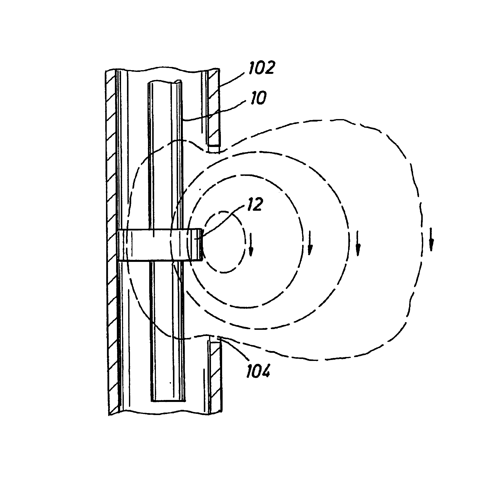
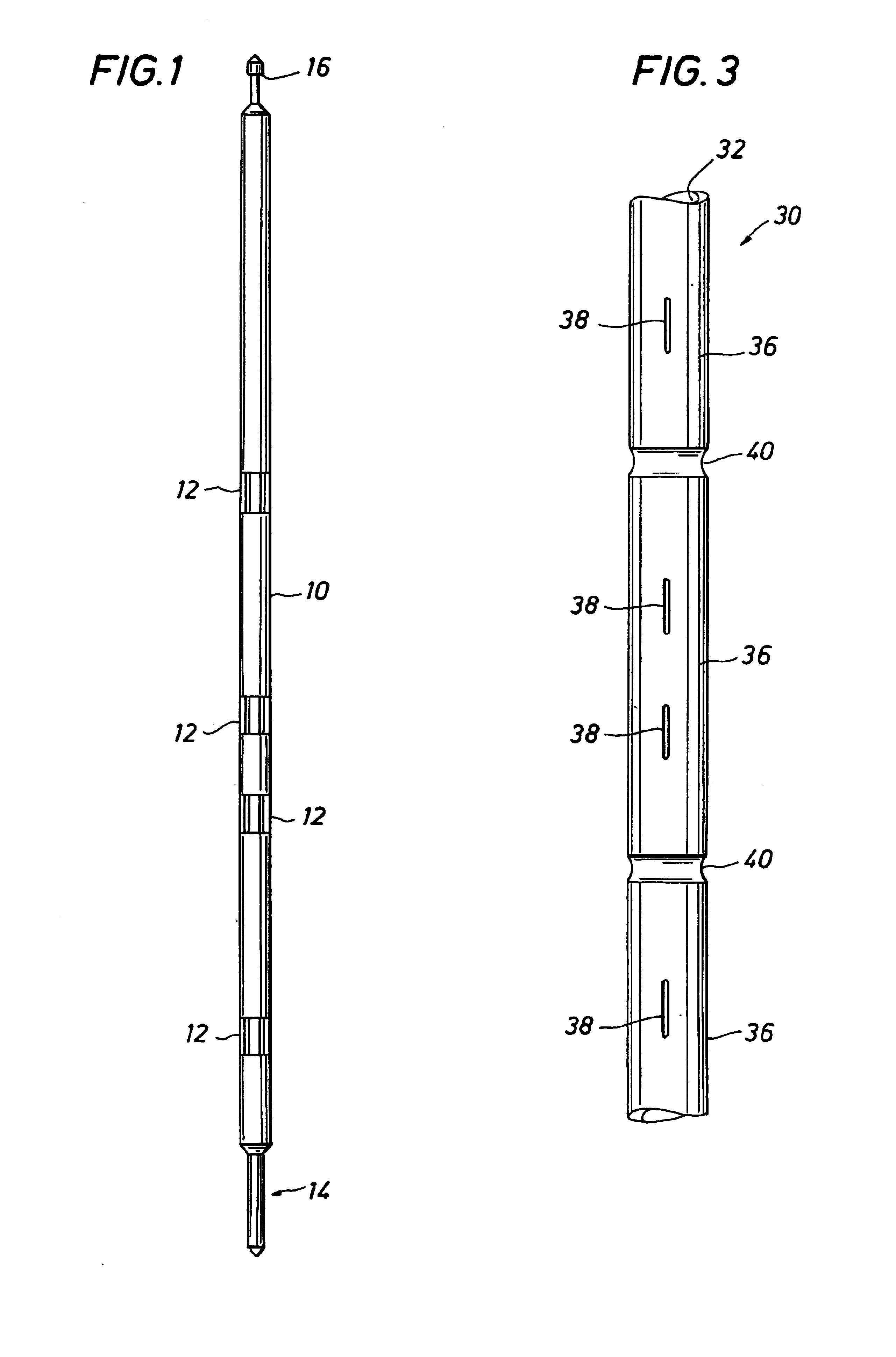
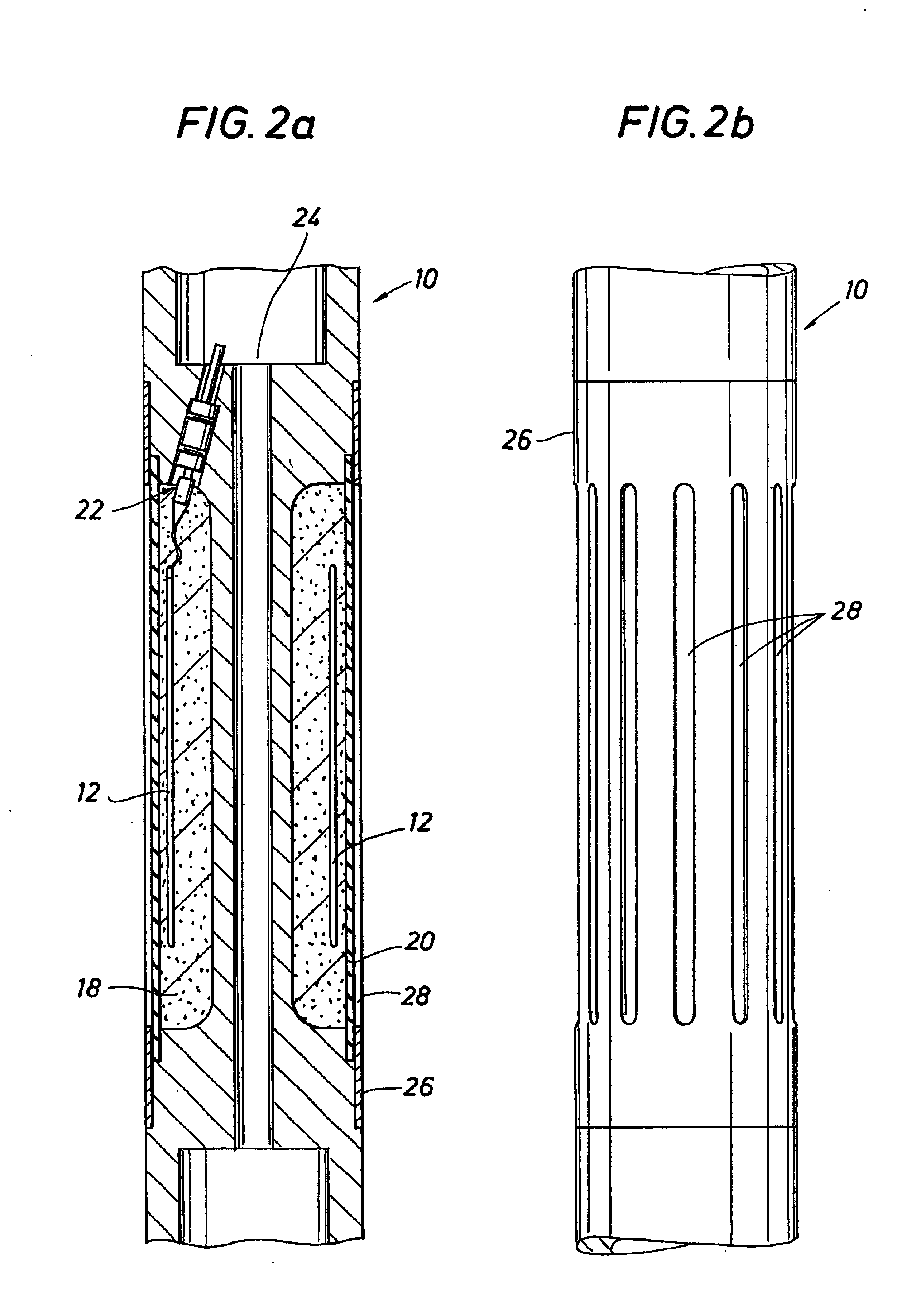
FIG. 1 shows an embodiment of the RIT 10 of the invention. The RIT 10 is an elongated, small-diameter, metallic support or mandrel that may contain one or more antennas 12, sources, sensors [sensor / detector are interchangeable terms as used herein], magnets, a gamma-ray detector / generator assembly, neutron-generating / detecting assembly, various electronics, batteries, a downhole processor, a clock, a read-out port, and recording memory (not shown).

The RIT 10 does not have the mechanical requirements of a drill collar. Thus, its mechanical constraints are greatly reduced. The RIT 10 has a landing mechanism (stinger) 14 on the bottom end and a fishing head 16 on the top. The fishing head 16 allows for the RIT 10 to be captured and retrieved from within a sub with the use of a conventional extraction tool such ...


PUM


Abstract

Method and system for subsurface logging utilizing a modified metallic tubular having an elongated body with tubular walls and a central bore adapted to receive a support member. The tubular including slotted stations to provide through-tubular signal transmission and / or reception. Pressure barrier means provide hydraulic isolation at the slotted stations. The support member is equipped with various sources and sensors, including an antenna adapted to generate a magnetic dipole moment with a transverse or controllable orientation, and adapted for engagement within the tubular. The apparatus is suitable for LWT, LWD, and TLC logging operations.

Description

1. BACKGROUND OF THE INVENTION1.1. Field of the InventionThis invention relates generally to the investigation of subsurface earth formations, and, more particularly, to techniques for determining formation properties using tilted or transverse magnetic dipole sources or sensors housed within a modified metallic tubular. This invention is applicable to induction or propagation type measurements, i.e., at low and high frequencies.1.2. Description of Related ArtResistivity and gamma-ray logging are the two formation evaluation measurements run most often in well logging. Such measurements are used to locate and evaluate the properties of potential hydrocarbon bearing zones in subsurface formations. In many wells, they are the only two measurements performed, particularly in low cost wells and in surface and intermediate sections of more expensive wells.These logging techniques are realized in different ways. A well tool, comprising a number of transmitting and detecting devices for me...

Claims


Application Information

Patent Timeline
Patent Type & Authority Patents(United States)
IPC IPC(8): E21B47/12E21B47/01E21B47/00G01V11/00G01V3/30
CPCE21B47/011G01V11/002G01V3/30E21B47/122E21B47/017E21B47/13
Inventor FREY, MARK T.OMERAGIC, DZEVATTABANOU, JACQUES R.
Owner SCHLUMBERGER TECH CORP
Learn More