Arrangement utilizing a magnetic attractive force

a magnetic attractive force and arrangement technology, applied in the direction of instruments, identification means, display means, etc., can solve the problems of particularly thin panels that are extremely difficult to handle, and achieve the effect of costing production

Inactive Publication Date: 2005-01-04
EXPAND INT
View PDF9 Cites 26 Cited by
  • Summary
  • Abstract
  • Description
  • Claims
  • Application Information

AI Technical Summary

Benefits of technology

The advantages that may primarily be deemed to characterise an arrangement in accordance with the present invention are that prerequisites are thereby created to assign a panel in a display system a rolled-up state wherein the radius of curvature can be chosen considerably smaller than the radius of curvature applicable for conventional rollable panels and wherein a modulus of elasticity and a thickness of said panel and a modulus of elasticity and a thickness of the magnetised strip or strips are such in relation to each other that only small axial stress related forces, or none at all, will act within said attachment means used.
It is furthermore advocated that the magnetised strip should be assigned a thickness which, at least in normal cases, shall be less than 1.0 mm.
Furthermore a strip arrangement having two sections may be used and the cost for the production of such a magnetic strip is less than for a full magnetic strip arrangement yet the adhesive attachment force may be the same.
The features primarily considered characteristic of an arrangement in accordance with the present invention are specified in the characterising part of claim 1.

Problems solved by technology

Thin panels in particular are extremely difficult to handle when fully rolled up since they become heavy at the end or edge due to the weight of the magnetic strips.

Method used


Image

  • Arrangement utilizing a magnetic attractive force
  • Arrangement utilizing a magnetic attractive force
  • Arrangement utilizing a magnetic attractive force

Examples


Embodiment Construction

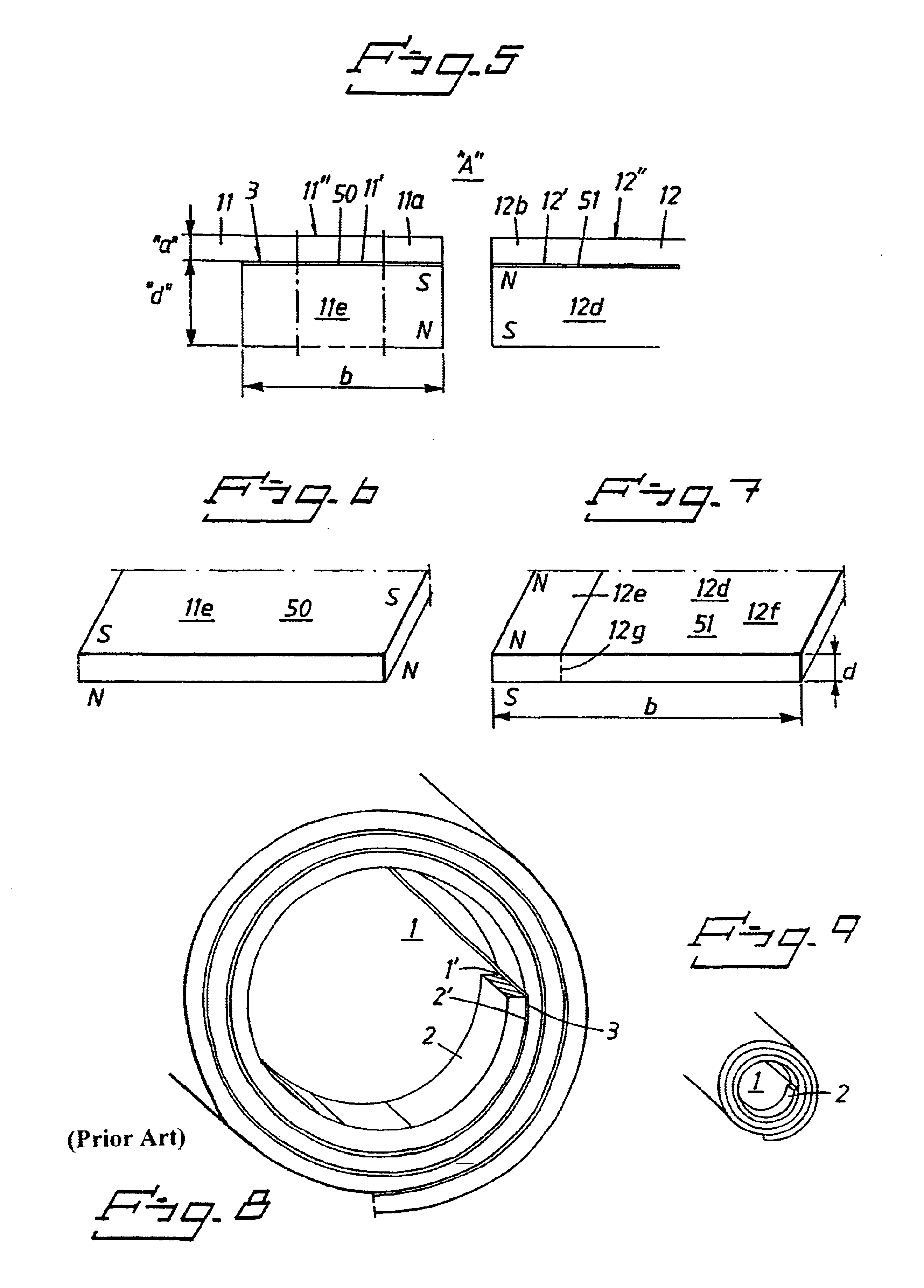
To start with, the axial stress related forces occurring when a “beam” B having rectangular cross section is subjected to stresses through bending or, in the present case rolling up or unrolling, will be described with reference to FIG. 1.

In this application a neutral plane or layer 2a will be located centrally. The axial stress forces “N−” and “N+” are here symmetrically distributed about the neutral layer 2a and increase in upward or downward direction therefrom.

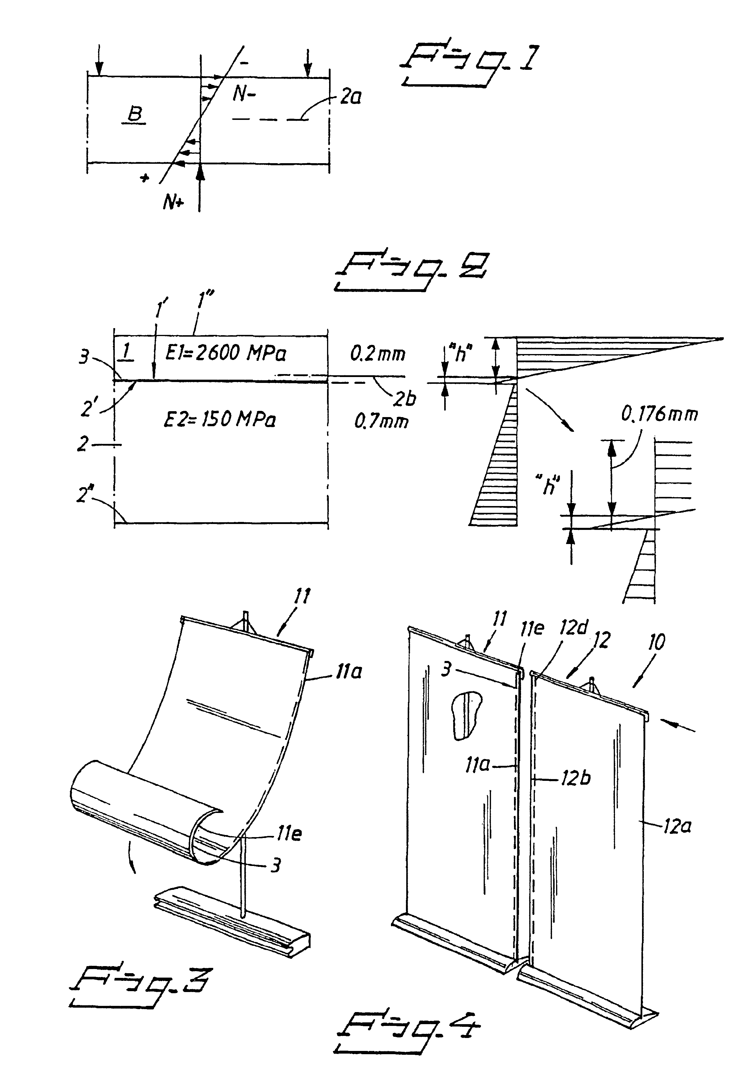
FIG. 2 is intended to illustrate the distribution of the axial stress forces for a panel 1 designed in accordance with the principles of the invention where, for the sake of clarity, we have chosen to illustrate the invention and the axial forces occurring by selecting a thickness of 02. mm and a modulus of elasticity of 2600 MPa for the panel 1, to which is attached a magnetic strip 2 selected here with a thickness of 0.7 mm and a modulus of elasticity of 150 MPa.

The neutral layer 2b for this combination will be situated ...


PUM


Abstract

The present invention relates to an arrangement enabling edge-to-edge joining, by means of a magnetic attractive force, of a first edge portion 811a) of a first panel (11) in a display system to a second edge portion (12b) of a second panel (12), a first magnetised strip (11e) being applied to said first edge portion (11a) and a second magnetised strip (12b) being applied to said second edge portion (12b). The magnetised strips (11e, 12d) are assigned such magnetisation directions (s-n; n-s) that, in a position where the edge portions are in proximity and/or co-operating with each other, they assume a position attracted to each other. Said strips (11e, 12d) consist of a material different from the material of the panel (11, 12). The modulus of elasticity and the thickness (2600 MPa; 0.2 mm) of said panel (11) and the modulus of elasticity and the thickness (100 MPa; 0.7 mm) of said strips (11e, 12d) are such that only small axial stress related forces, or none at all, will act within the attachment means (50, 51). Said strips (11e, 12d) are assigned a thickness (“d”) of less than 1.0 mm.

Description

TECHNICAL FIELDThe present invention relates generally to an arrangement based in principle on utilising a magnetic attractive force when it becomes operative between two permanently magnetised or magnetic strips.More specifically the present invention relates to an arrangement enabling edge-to-edge joining or holding together, by means of a magnetic attractive force, of a first edge portion of a first panel in a display system to or against an opposed or second edge portion of a second panel.The arrangement in accordance with the invention is also based on the principle of a first magnetised strip being applied to said first edge portion and a second magnetised strip being applied to said second edge portion, the edge-oriented magnetised strips being assigned such magnetisation directions that, in a position where the edge portions are in proximity and / or co-operating with each other, they assume a position strongly attracted to each other.The principle of the invention is also bas...

Claims


Application Information

Patent Timeline
Patent Type & Authority Patents(United States)
IPC IPC(8): G09F15/00G09F7/02G09F7/04
CPCG09F15/00G09F7/04
Inventor ZARELIUS, CHRISTER
Owner EXPAND INT
Why Eureka
Try Eureka