Calendar for a sheet of paper
a technology for a calendar and which is applied in the field of calendars for a sheet of paper, can solve the problems of sleeve b>2/b> being easily slipped, gaps being produced, and deformation of the sleeves
- Summary
- Abstract
- Description
- Claims
- Application Information
AI Technical Summary
Benefits of technology
Problems solved by technology
Method used
Image

Examples
sixth embodiment
Now, the present invention will be described with reference to FIGS. 8A and 8B.
FIGS. 8A and 8B show the contact surfaces of the support rolls of a calender constructed in accordance with the sixth embodiment of the present invention. In the sixth embodiment, the support shoe in the above-described fifth embodiment of FIG. 7 is provided with grooves. Since the remaining construction is the same as the fifth embodiment, a description will be given of different parts.
A support shoe 180 shown in FIG. 8A is disposed inside the jacket 101 of FIG. 7 at the position opposite to the driving roll 130 of FIG. 7. The outer periphery of the support shoe 180 is provided with grooves 182, which extend in a direction where the above-described jacket 101 rotates.
A support shoe 181 in FIG. 8B, as with the support shoe 180 of FIG. 8A, is disposed inside the jacket 101 of FIG. 7 at the position opposite to the driving roll 130 of FIG. 7. The outer periphery of the support shoe 181 is provided with groo...
seventh embodiment
Now, the present invention will be described with reference to FIGS. 9 and 10.
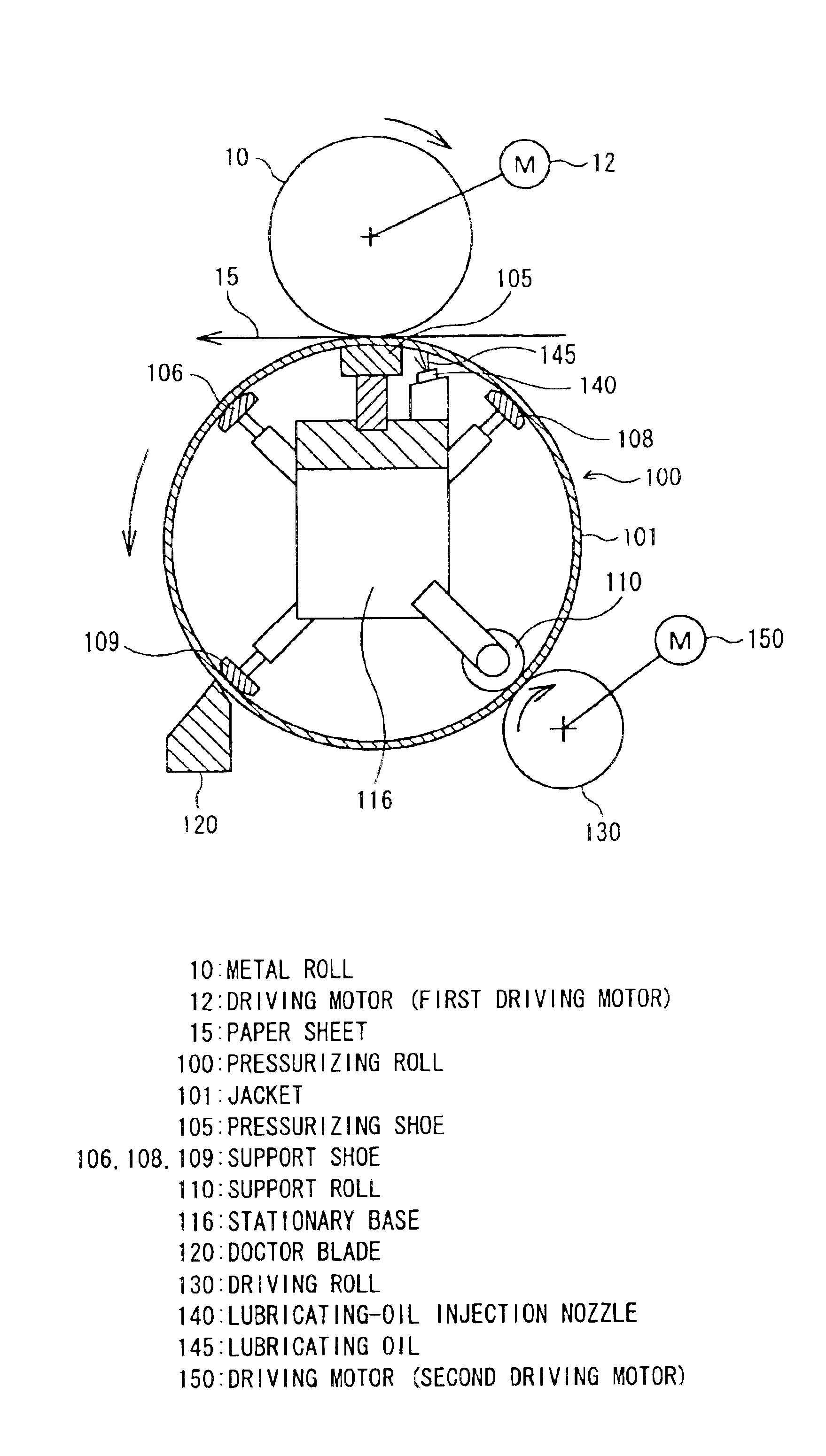
FIG. 9 shows a calender constructed in accordance with the seventh embodiment of the present invention. FIG. 10 shows the support roll of the calender. In the seventh embodiment, the number of support shoes in the above-described first embodiment is increased to hold a jacket 101. At the position opposite to a driving roll 130, a support member is provided with a rotatable roll. Since the remaining construction is the same as the first embodiment, a description will be given of different parts. Note in FIGS. 9 and 10 that the same parts as FIGS. 1 and 2 are represented by the same reference numerals.
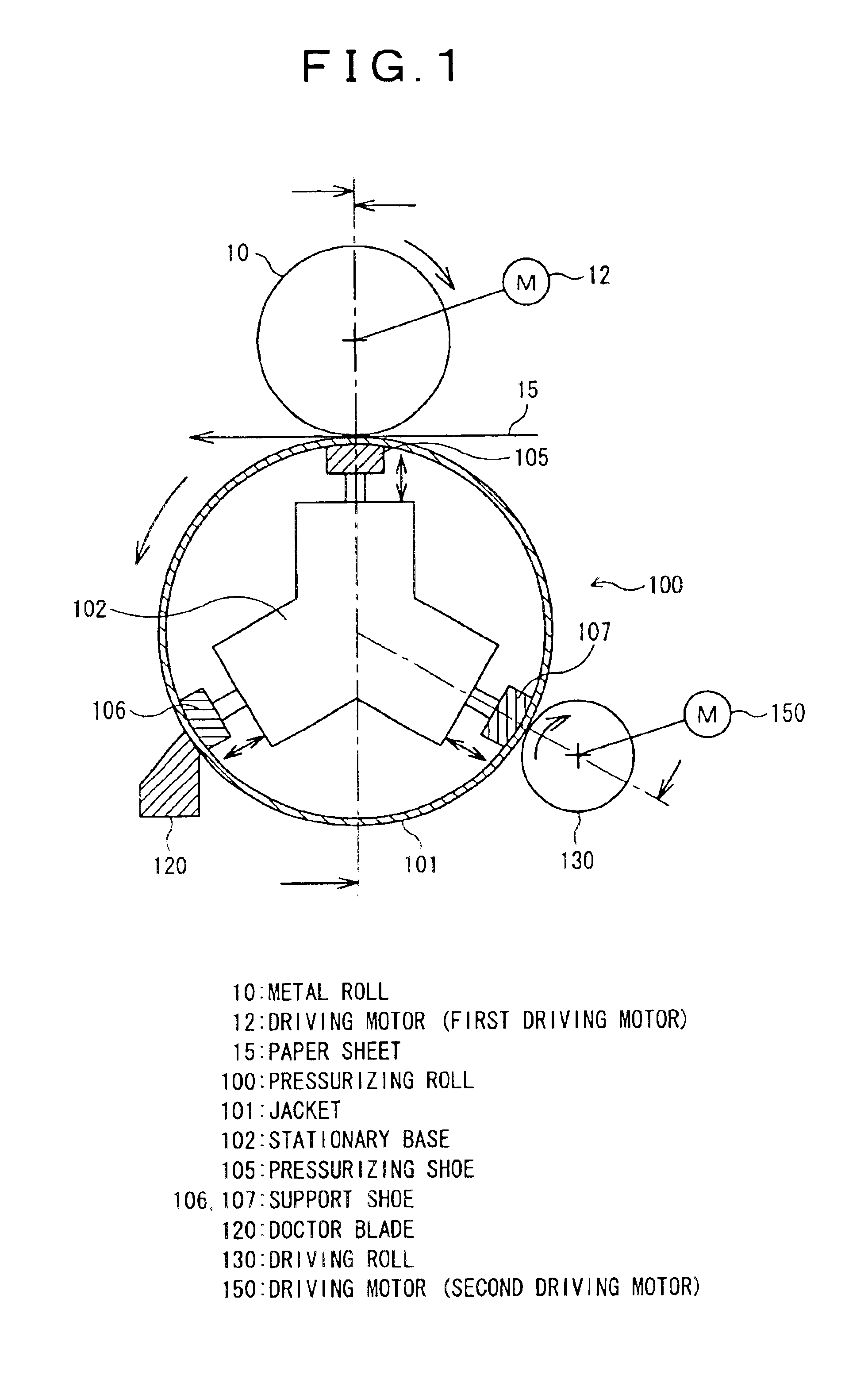
A rotatable metal roll 10 and a pressurizing roll 100 are disposed at the opposite positions through a paper sheet 15. The outer periphery of the pressurizing roll 100 is provided with a resin jacket 101. Inside the jacket 101, there is provided a stationary base 116.
A recessed, pressurizing shoe 105 and suppor...
eighth embodiment
Now, the present invention will be described with reference to FIGS. 11A and 11B.
FIGS. 11A and 11B show the support rolls of a calender constructed in accordance with the eighth embodiment of the present invention, respectively. In the eighth embodiment, the support roll 110 in the above-described seventh embodiment of FIG. 10 is provided with grooves. Since the remaining construction is the same as the seventh embodiment, a description will be given of different parts.
A support roll 111 shown in FIG. 11A is disposed inside the jacket 101 of FIG. 10 at the position opposite to the driving roll 130 of FIG. 10. The outer periphery of the support roll 111 is provided with grooves 113, which extend in the peripheral direction.
A support roll 112 in FIG. 11B, as with the support roll 111 of FIG. 11A, is disposed inside the jacket 101 of FIG. 7 at the position opposite to the driving roll 130 of FIG. 7. The outer periphery of the support roll 112 is provided with grooves 114, which extend ...
PUM
| Property | Measurement | Unit |
|---|---|---|
| Speed | aaaaa | aaaaa |
| Torque | aaaaa | aaaaa |
Abstract
Description
Claims
Application Information
 - R&D
- Intellectual Property
- Life Sciences
- Materials
- Tech Scout
- Unparalleled Data Quality
- Higher Quality Content
- 60% Fewer Hallucinations
Browse by: Latest US Patents, China's latest patents, Technical Efficacy Thesaurus, Application Domain, Technology Topic, Popular Technical Reports.
© 2025 PatSnap. All rights reserved.Legal|Privacy policy|Modern Slavery Act Transparency Statement|Sitemap|About US| Contact US: help@patsnap.com