

V-engine supercharging device
a supercharging device and engine technology, applied in the direction of machines/engines, mechanical equipment, combustion air/fuel air treatment, etc., can solve the problems of inability to form the space for building the butterfly valve in the supercharging device, the actuator for driving the butterfly valve cannot be mounted on the outside, and the durability is not good,
- Summary
- Abstract
- Description
- Claims
- Application Information
AI Technical Summary
Problems solved by technology
Method used
Image

Examples
Embodiment Construction
The present invention will be described in detail with reference to the accompanying drawings.
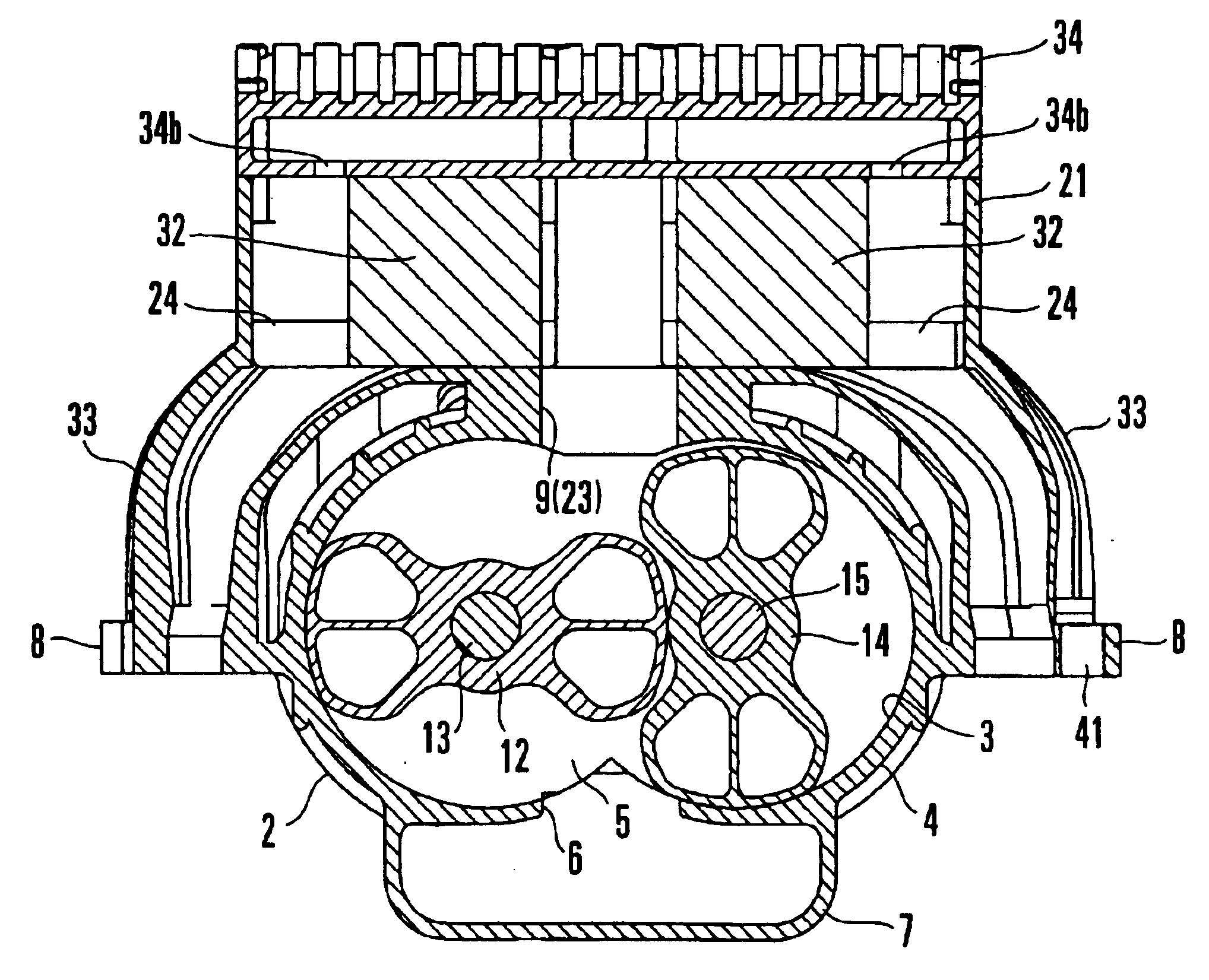
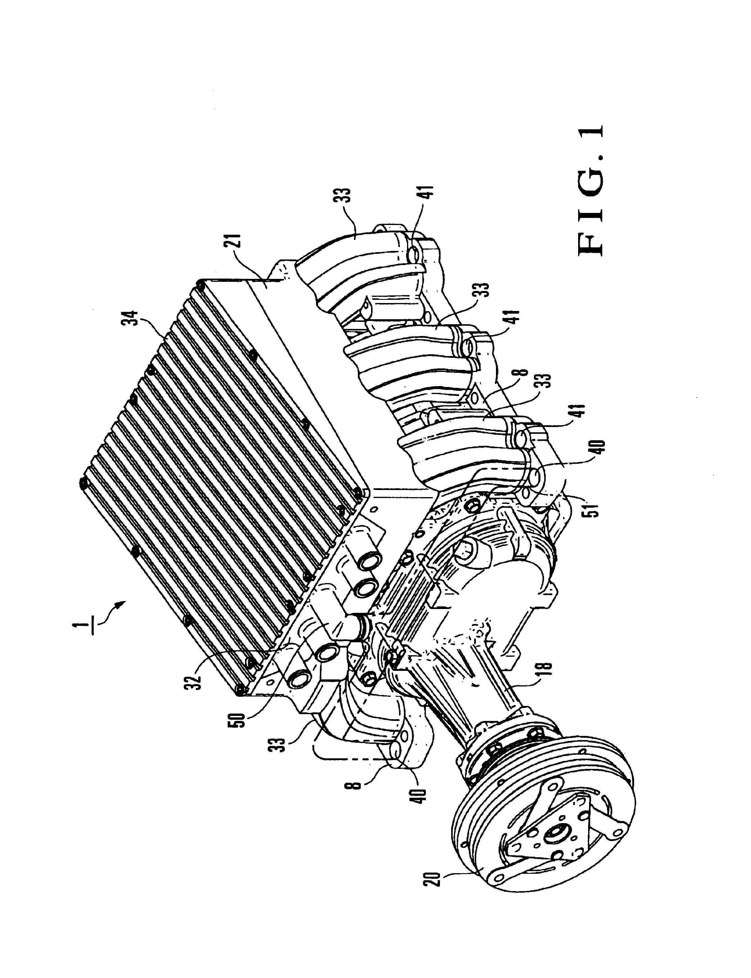
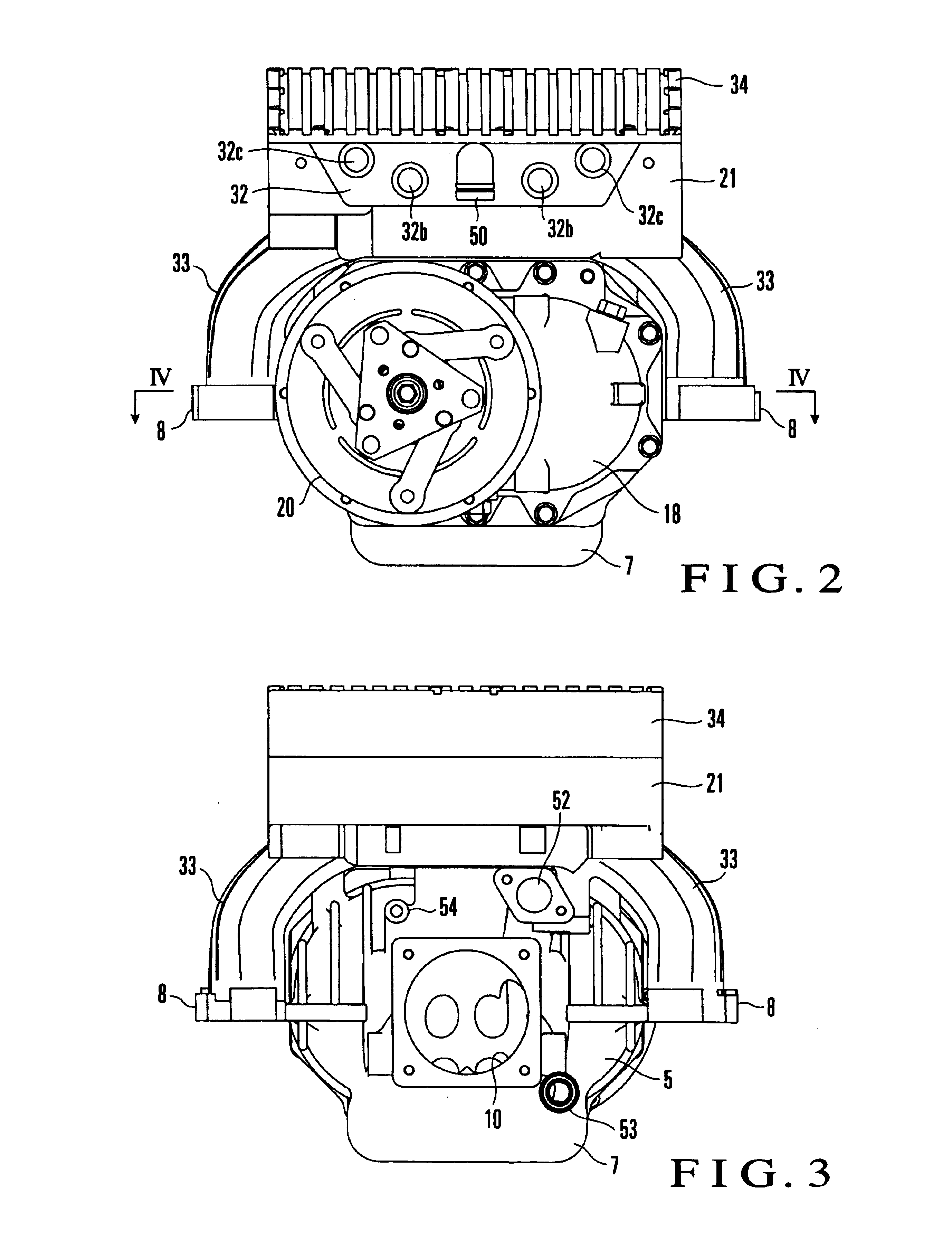
FIGS. 1 to 10C show a V-engine supercharging device according to an embodiment of the present invention. In this embodiment, as a V-engine supercharging device, a mechanical roots blower which is driven by the power from a crank shaft is shown. As shown in FIGS. 1, 2, and 6, a supercharging device 1 according to this embodiment has a housing in which a rotor housing 2, collector housing 21, and six suction pipes 33 are integrally manufactured by aluminum alloy casting, and a collector cover 34 which closes the upper opening of the collector housing 21 and is manufactured by aluminum alloy casting. As shown in FIGS. 4 and 5, the supercharging device 1 also has a front housing 11 which closes the front-side opening of the rotor housing 2, and a nose pipe 18 disposed on the front side of the front housing 11 and fixed to the rotor housing 2 with bolts.
As shown in FIG. 6, the rotor housing 2 ha...
PUM
 Abstract
Description
Claims
Application Information