Method for adaptive triggering of a breathing device, and breathing device with adaptive triggering

a breathing device and adaptive triggering technology, applied in the direction of valves, respirators, mechanical devices, etc., can solve the problems of less delay, delay time, unsatisfactory, etc., and achieve the effect of improving the trigger method

Inactive Publication Date: 2005-01-04
MAQUET CRITICAL CARE
View PDF29 Cites 32 Cited by
  • Summary
  • Abstract
  • Description
  • Claims
  • Application Information

AI Technical Summary

Benefits of technology

It is an object of the invention to provide a method that improves the trigger methods described above.
A combination of these two is of course possible. For instance, a certain level in the excitable cell signal (which could be lower than the trigger threshold for known systems using only such signals for triggering) starts a window in which triggering can take place. As the signal level increases (as the case is if inspirations are concerned) the flow and / or pressure trigger level will be changed toward higher sensitivity. This makes it possible to use a higher sensitivity and yet minimize the risk of self-triggering due to signal disturbances.
A pressure dependent flow control also can be used in addition to the adaptation made on basis of the excitable cell signal. Particularly in view of progress in the development of extremely small and accurate pressure sensor, it has now become realizable to carry out pressure measurements within the lungs. Pressure measurements have thus become more reliable and usable.

Problems solved by technology

Although these systems normally operate satisfactorily, there will be a delay time from the actual onset of a spontaneous inhalation attempt (originating in the respiratory center of the brain) until triggering actually occurs.
The primary part of the delay, however, is due to the fact that triggering levels are set high enough to avoid any risk of self-triggering (i.e. the device being triggered to start an inspiration phase when there is no attempt made by the patient).
The latter two have less delay, but are not ideal in all situations.
Measuring activity in all muscles related to respiration is not realistic.

Method used


Image

  • Method for adaptive triggering of a breathing device, and breathing device with adaptive triggering
  • Method for adaptive triggering of a breathing device, and breathing device with adaptive triggering
  • Method for adaptive triggering of a breathing device, and breathing device with adaptive triggering

Examples


Embodiment Construction

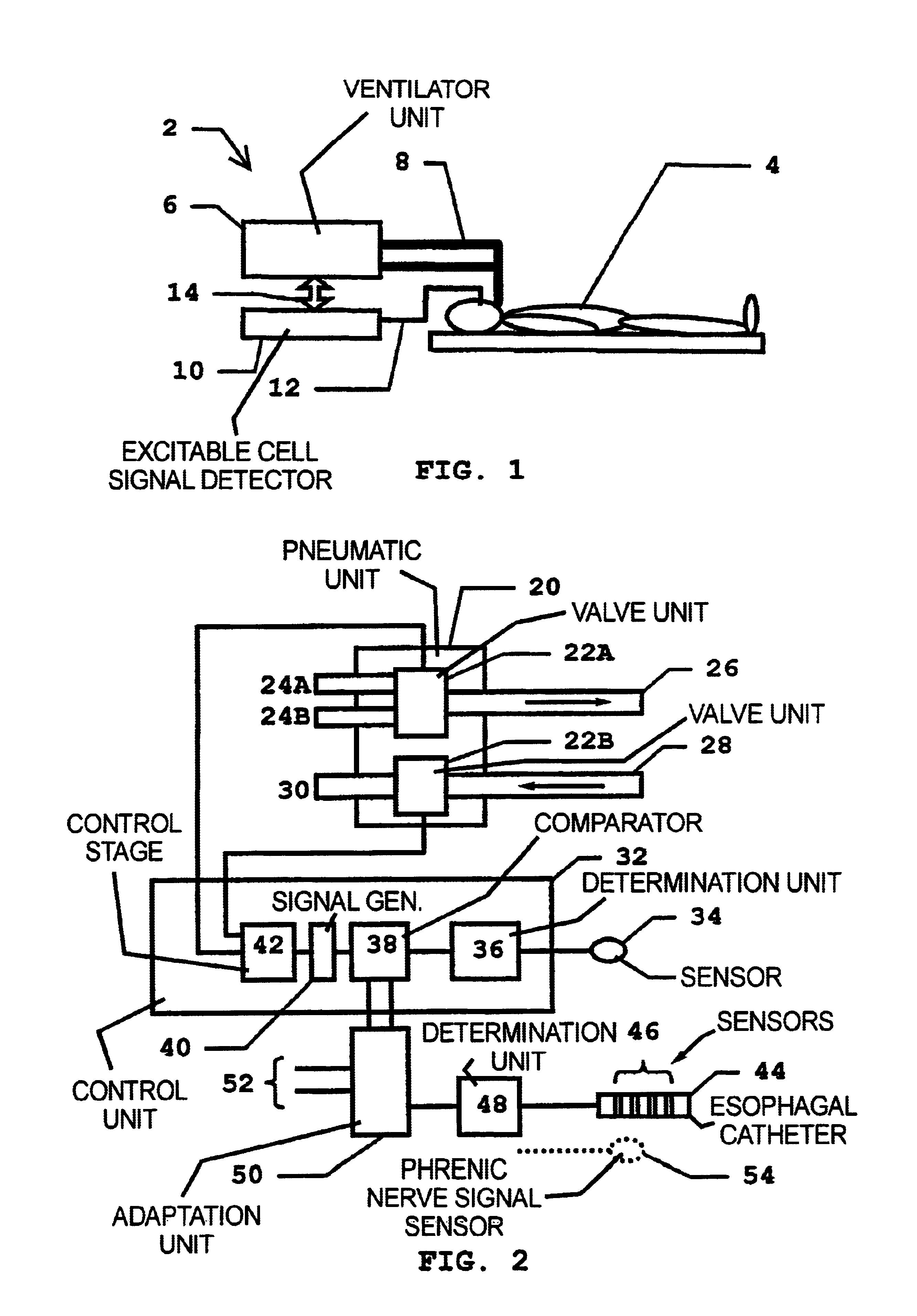
A breathing device 2 according to the invention is shown in FIG. 1. The breathing device 2 has in this embodiment a ventilator unit 6 connected to a patient 4 for delivering breathing gas to and removing breathing gas from the patient 4. Connection is in this case illustrated with a conventional tubing system 8 that can be connected to the patient via a tracheal tube, tracheotomy tube, face mask, etc.

Also connected to the patient 4 is an excitable cell signal detector 10, in this embodiment an esophageal diaphragm electromyography detector. The excitable cell signal detector 10 is connected to the patient 4 via a catheter lead 12 and can communicate with the other parts of the breathing device via a communication link 14.

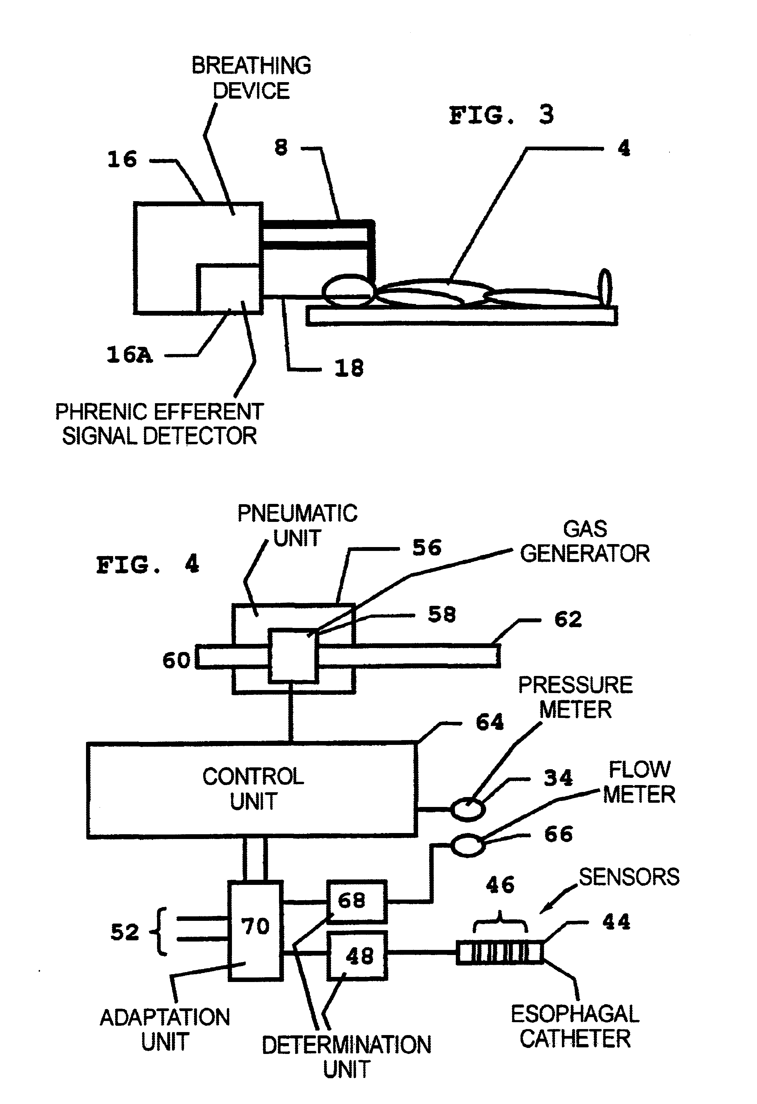
Another embodiment of the breathing device is shown in FIG. 3. Here the breathing device 16 includes all parts within the same enclosure. As with the breathing device 2, a conventional tubing system 6 connects the breathing device 16 to a patient 4.

In this second em...


PUM


Abstract

In a method for adaptive triggering of respiratory phases in a breathing device, and a breathing device operating according to the method, first respiration indicator signal is determined based on at least one of the parameters flow and pressure, the respiration indicator signal is compared with a trigger requirement and a trigger signal is generated when the respiration indicator signal fulfils the trigger requirement. In order to shorten response times to respiration changes without losing stability, an excitable cell signal related to respiration is measured, and a second respiration indicator signal is determined based on the measured excitable cell signal, and the trigger requirement is adapted in relation to the second respiration indicator signal.

Description

BACKGROUND OF THE INVENTION1. Field of the InventionThe present invention relates to a method for adaptive triggering of A breathing device as well as to a breathing device operating according to the method.2. Description of the Prior Art“Triggering” as used herein means the activation of any respiration phase, i.e. both inspiration phases and expiration phases. This is a broader meaning than that normally understood by the term (triggering is normally only related to the activation of inspiration phases).“Breathing device” as used herein means all known devices providing a breathable gas to a subject. This includes, inter alia, ventilators, respirators, anaesthetic machines and resuscitation devices.State of the art breathing devices have a triggering functionality based on the gas parameters flow and pressure.A flow triggering system is known from European Application 0 459 647, which discloses a breathing ventilator where a predetermined rate of flow of gas is delivered toward a ...

Claims


Application Information

Patent Timeline
Patent Type & Authority Patents(United States)
IPC IPC(8): A61M16/00A61M16/12A61M16/10
CPCA61M16/00A61M16/12A61M2016/0021A61M2230/60A61M2230/65A61M2230/005A61M16/0063A61M16/024
Inventor SAMZELIUS, ROGER
Owner MAQUET CRITICAL CARE
Why Eureka
Try Eureka