Ladder safety device

a safety device and ladder technology, applied in the field of ladder safety devices, can solve the problems of dangerous use of permanent bolts, building fascia, and use of bolts in the building's fascia

Inactive Publication Date: 2005-01-04
GROVER STEVEN BARRY
View PDF6 Cites 34 Cited by
  • Summary
  • Abstract
  • Description
  • Claims
  • Application Information

AI Technical Summary

Benefits of technology

It is therefor the object of the invention the provide a safety device for ladders that will stabilize t

Problems solved by technology

A disadvantage of the “774” patent is the use of permanent bolts, where the fascia of a building is damaged, and must be repaired after the removal of the assembly.
Another disadvantage of the “774” patent is that the

Method used


Image

  • Ladder safety device
  • Ladder safety device
  • Ladder safety device

Examples


Embodiment Construction

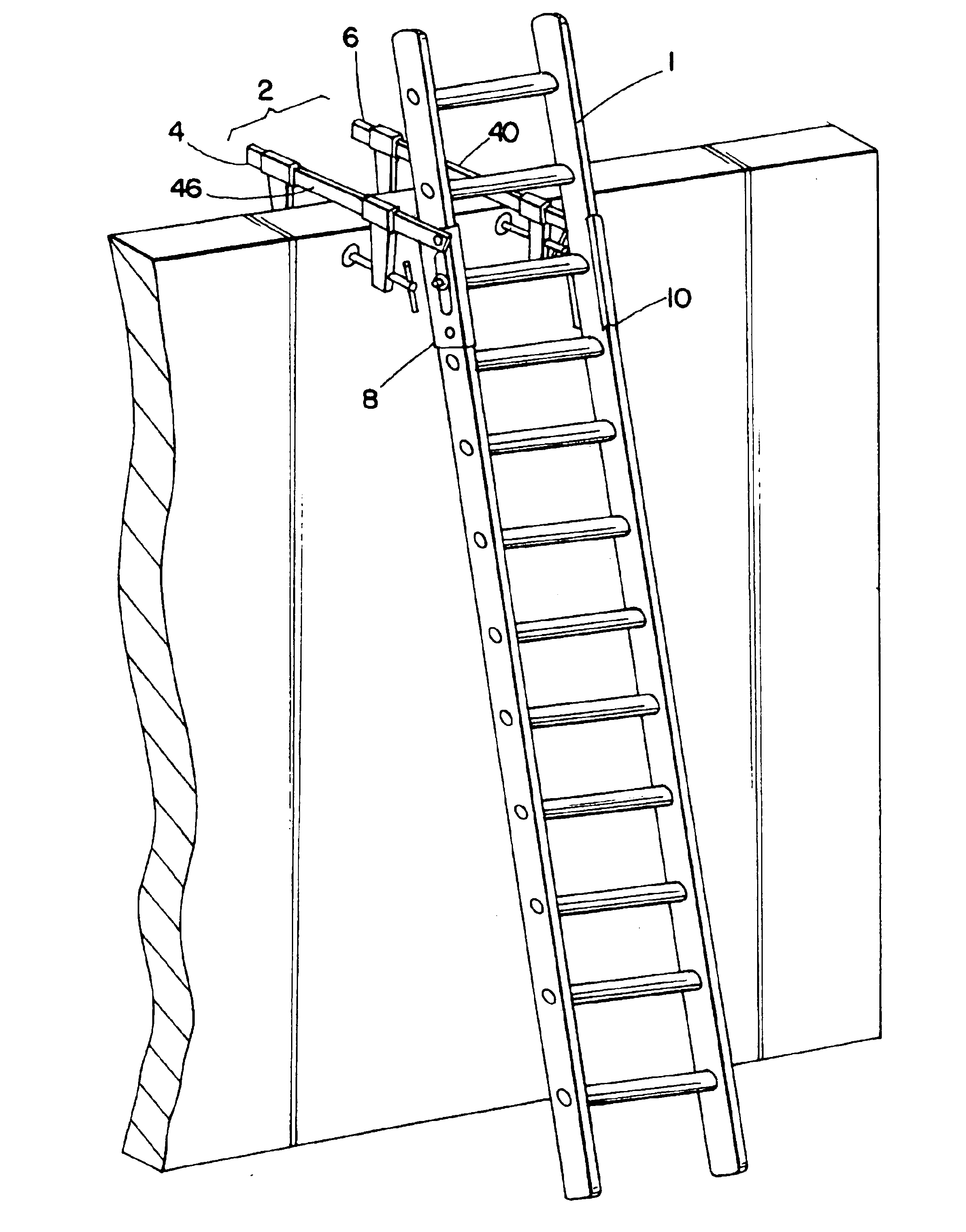
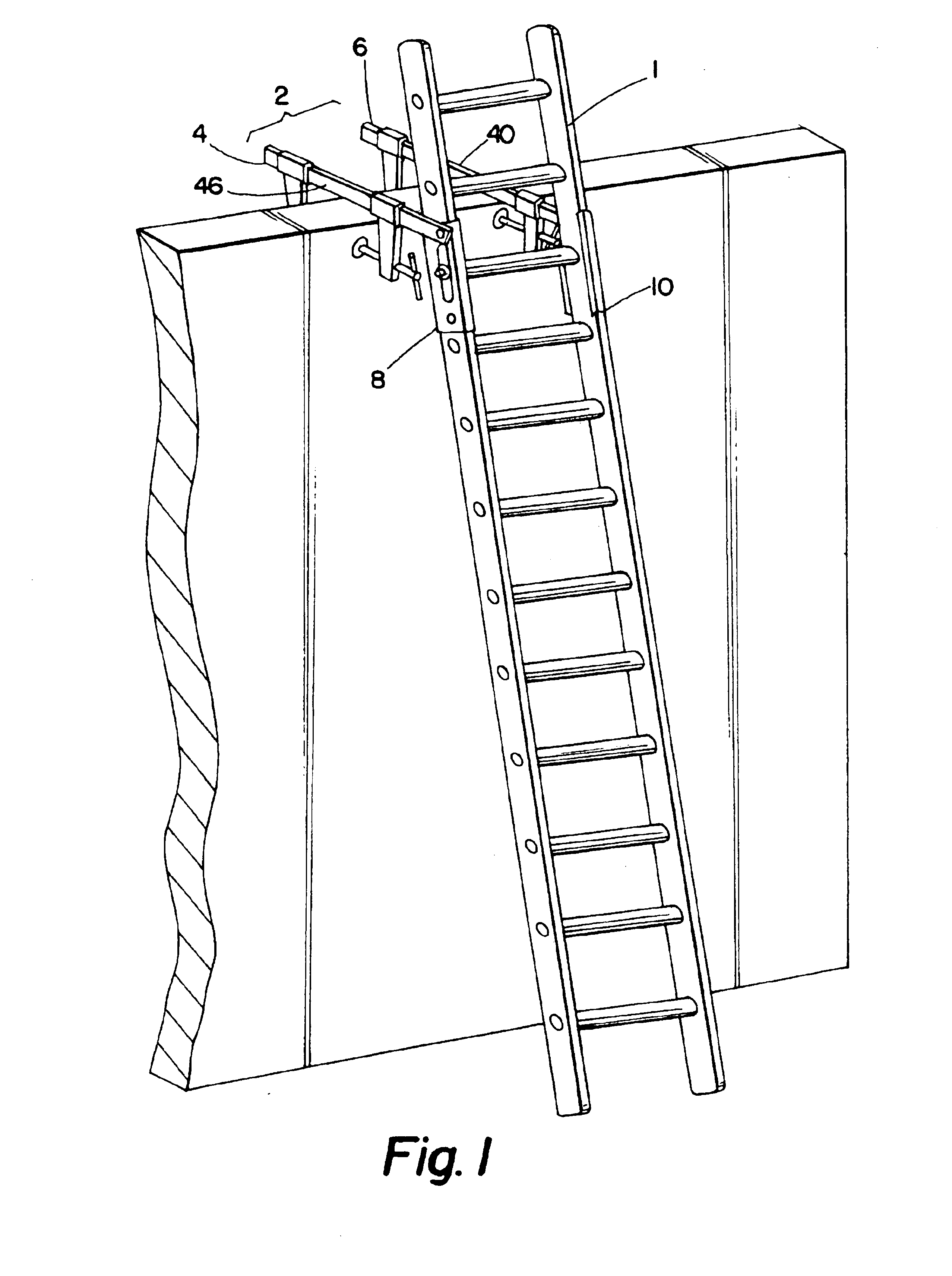
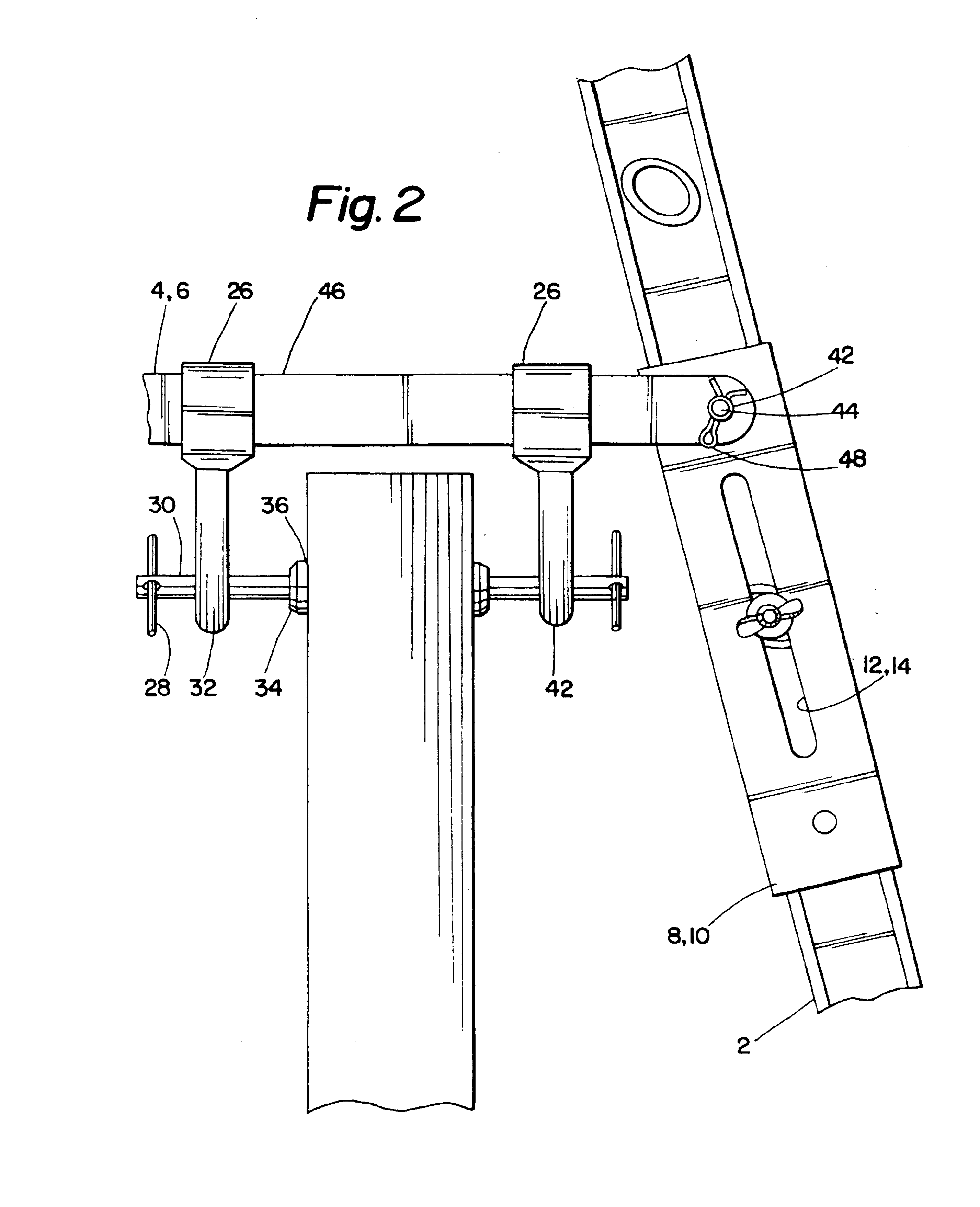
With respect to FIG. 1, a ladder (1) is shown leaning against a wall. A ladder safety device (2) is shown having a first sliding bar clamp (4), and a second sliding bar clamp (6). The first sliding bar clamp (4) is shown pivotably mounted to a first clamp plate (8). The second sliding bar clamp (6) is shown pivotably mounted to a second clamp plate (10). The first and second sliding bar clamp (4, 6) each have a bar (46). The bar (46) of the first and second sliding bar clamp (4, 6) each has a hole (42) defined therein. A pivot pin (44) is inserted through the hole (42) in the bar (46) thereby pivotably securing the first and second sliding bar clamp (4, 6) to the first and second clamp plates (8, 10) respectively. A standard cotter pin (48) may be used to prevent dislocation of the first and second sliding bar clamp (4, 6) from the first and second clamp plates (8, 10) respectively.

The first clamp plate (8) has a first elongated slot (12) defined therein, and the second clamp plate ...


PUM


Abstract

My invention will secure a ladder to a building or roof and will not slide or come loose. Saving Lives.

Description

1. BACKGROUND OF THE INVENTIONThis invention relates to a safety device that will prevent unwanted movement of a ladder when it is positioned against a building structure, storage tank, utility pole or the like. This invention will stabilize the upper portion of the ladder and thereby prevent the ladder from being dislocated. The invention generally consists of a pair of brace plates, where each brace plate is positioned on opposing sides of each ladder rail. A pair of clamps are mounted onto the brace plates. The clamps will be secured onto the building, and the brace plates will be clamped on either side of the ladder using a through rod. The through rod is inserted through the ladder rungs. Generally the ladder rungs are hollow for strength on metallic ladders. This secures the ladder to the structure, preventing the ladder from being dislocated from its desired position, allowing a user to climb the ladder safely.2. DESCRIPTION OF THE PRIOR ART.Devices to stabilize ladders are k...

Claims


Application Information

Patent Timeline
IPC IPC(8): E06C1/34E06C7/48E06C1/00E06C7/00
CPCE06C7/48E06C1/34
Inventor GROVER, STEVEN BARRY
Owner GROVER STEVEN BARRY
Why Eureka
Try Eureka