Friction control for articulating arm joint

Inactive Publication Date: 2005-01-04
MIDMARK
View PDF13 Cites 32 Cited by
  • Summary
  • Abstract
  • Description
  • Claims
  • Application Information

AI Technical Summary

Benefits of technology

The present invention provides a friction control mechanism for the connecting joints in an articulating arm, so as to stop the piece of equipment held by the articulating arm from drifting away from its set position. The friction control mechanism includes a pivot connector attached to an arm with a pivot pin, an axial washer placed around the pivot pin and between the arm and the pivot connector, and two set screws threaded through the arm. The set

Problems solved by technology

One problem with existing articulating arms is that they tend to permit drift, so that the piece of equipment being held by the arm loses its set position after the operator moves the equipment to the desired location and releases it.
This is a particular problem with articulating arms used with dental x-ray machines.
Before the operator is able to activate the x-ray machine, the articulating

Method used


Image

  • Friction control for articulating arm joint
  • Friction control for articulating arm joint
  • Friction control for articulating arm joint

Examples


second embodiment

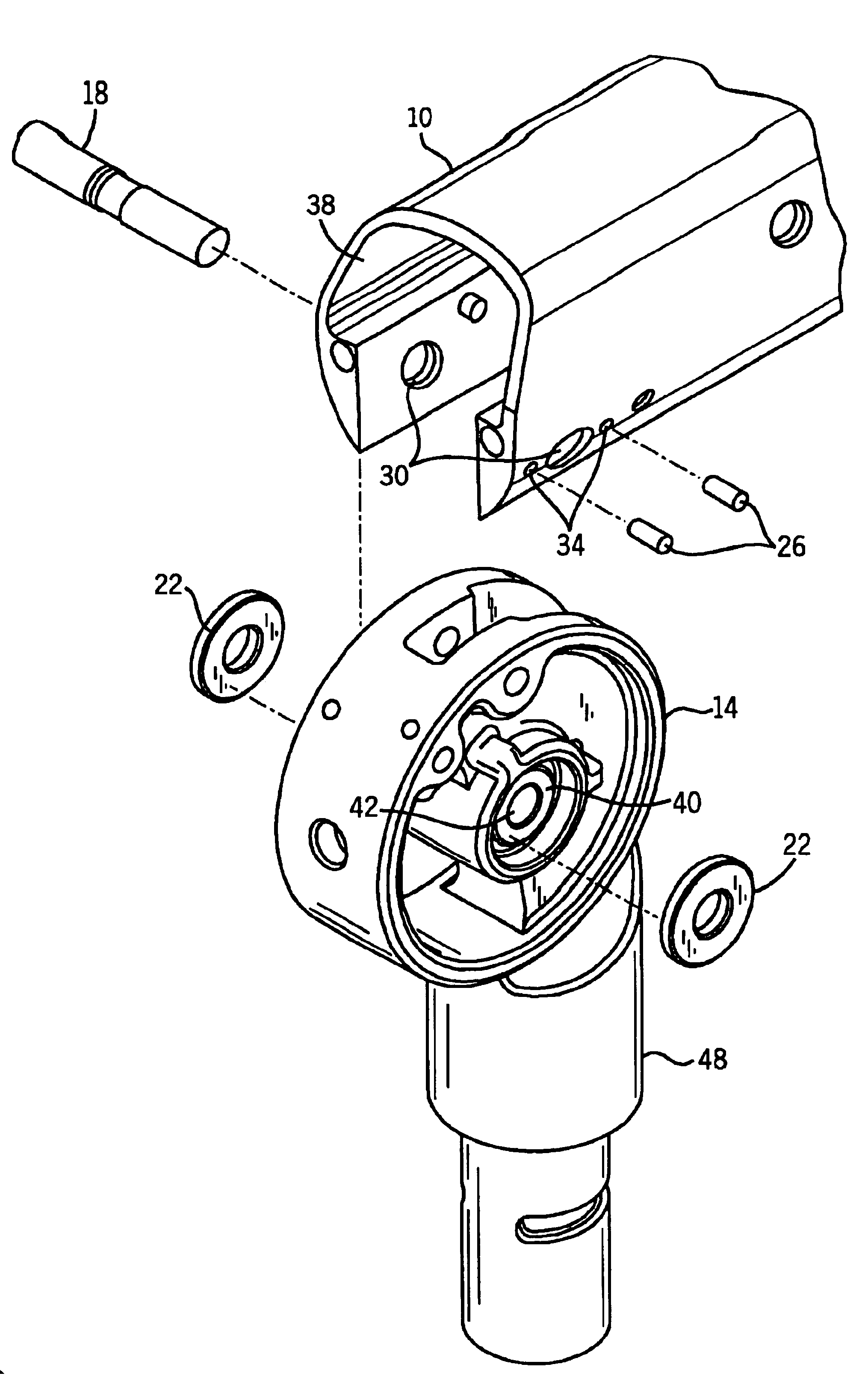
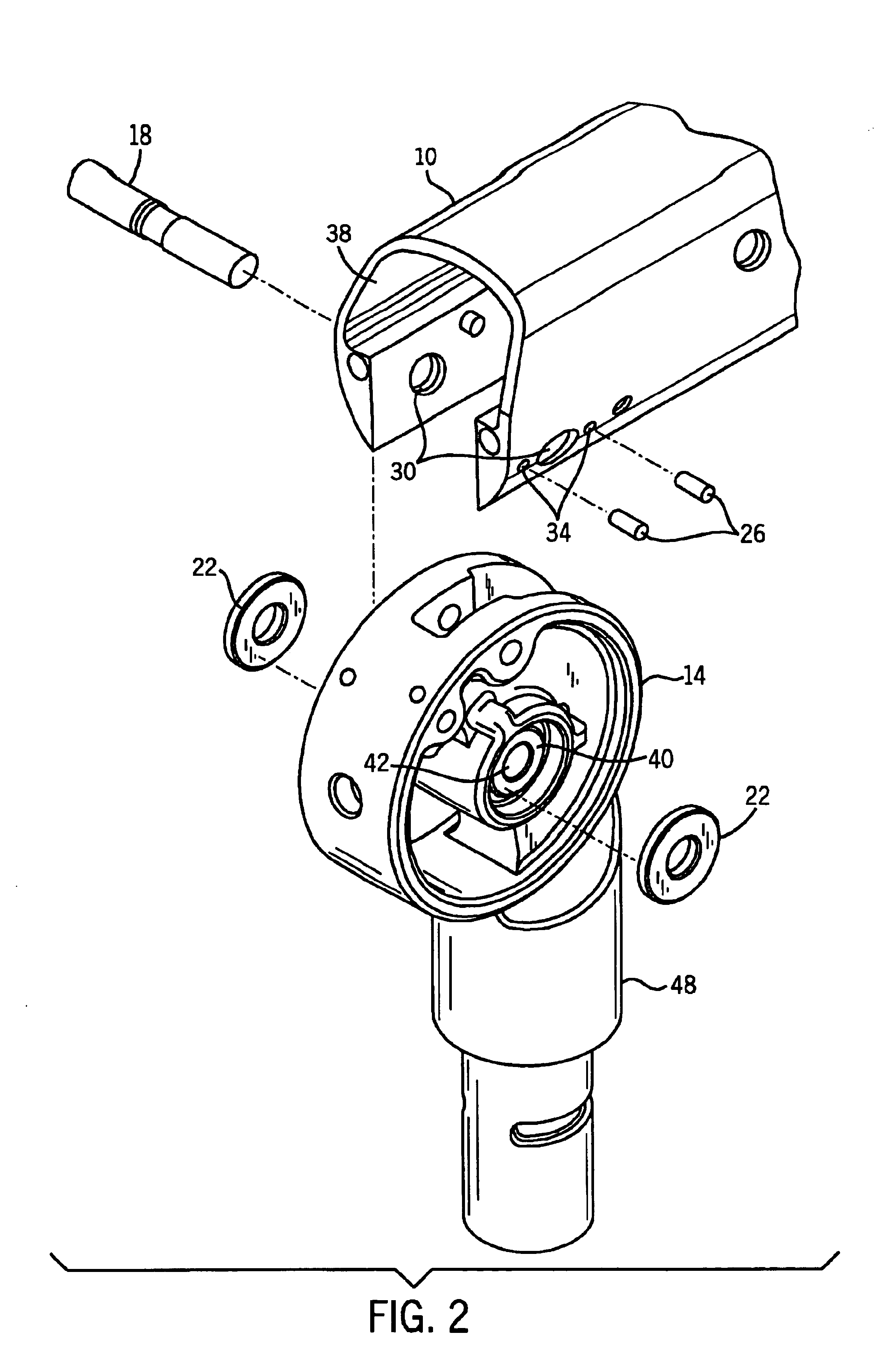
the invention may be used with joints requiring two pivot connectors as illustrated in FIGS. 4 and 5, FIG. 4 being an exploded view and FIG. 5 being a cross-sectional view. As there shown, the pivot connector 14 is connected to a second pivot connector 14 by a coupler 46. The second pivot connector 14 is connected to a second arm 10 by a second pivot pin 18. An axial washer 22 is applied about each end of the pivot pin 18, between the sides 38 of the second arm 10 and the flat surface 40 of the second pivot connector 14. Two set screws 26 are threaded through two threaded holes 34, contacting the axial washer 22.

The pivot connector is preferably formed of cast aluminum and the axial washers are preferably formed of stainless steel. Other material combinations are possible, but many do not work as well. For example, both aluminum-on-aluminum and aluminum-on-brass tend to bond and score or result in excessive wear.


PUM


Abstract

A friction control mechanism for an articulating arm including an arm, a pivot connector, an axial washer, and at least one set screw. An axial washer is placed around each side of a center aperture in the pivot connector. The pivot connector is connected to the arm with a pivot pin through the center aperture in the pivot connector and aligned holes in the first and second sides of the arm. At least one threaded hole is located adjacent the aligned hole in the first side of the arm. A set screw is placed through each threaded hole, making contact with the axial washer. This contact creates a friction force between the pivot connector and the axial washer, keeping the articulating arm from drifting away from its set position. The pivot connector may be connected to another device such as another arm or a machine such as an x-ray machine, or to another pivot connector.

Description

BACKGROUND OF INVENTIONThis invention relates generally to articulating arms for movably connecting a first body to a second body, specifically to a friction control mechanism for permitting close control of the friction at a joint of an articulating arm, allowing the articulating arm to hold the second body in a set position with respect to the first body after movement.Articulating arms that extend between a first body and a second body are well known in the art. Dental x-ray machines, for example, often use such articulating arms. The dental x-ray machine often has an x-ray machine head that must be located next to the patient's jaw while in use. Further, it must maintain that position without being held there by an operator, so that the operator can move behind a screen so as to be protected from the x-rays when the machine is operating. When the x-ray machine is not in use, the x-ray machine head must be moved to a location that will not interfere with the rest of the dentist's...

Claims


Application Information

Patent Timeline
IPC IPC(8): F16C11/10F16C11/04F16M11/06F16M11/02A61B6/14
CPCF16M11/06F16C11/103A61B6/14F16M2200/022
Inventor KANTOR, ARKADYKLEINSCHMIDT, JAMES W.
Owner MIDMARK
Why Eureka
Try Eureka