Anti-pumping dispense valve

a technology of dispense valve and liquid, which is applied in the direction of diaphragm valve, engine diaphragm, operating means/release devices of valves, etc., can solve the problems of product damage, cavitation and/or seepage of liquid,

Inactive Publication Date: 2005-01-04
SAINT GOBAIN PERFORMANCE PLASTICS CORP
View PDF3 Cites 57 Cited by
  • Summary
  • Abstract
  • Description
  • Claims
  • Application Information

AI Technical Summary

Benefits of technology

Dispense valves of this invention are referred to as an “anti-pumping” valves because the closing movement of the poppet (in the first dispense valve embodiment), and the combined movement of the poppet and the means for controlling volume (in the second dispense valve embodiment) do not operate to push or “pump” and additional and unwanted volume of liquid from the valve after it has been closed.

Problems solved by technology

It is, however, known in the industry that dispense valves used to perform this function do not always terminate the dispensement of liquid after the valve is closed or shut.
For example, conventional dispense valves used in this capacity are known to cavitate and/or seep out a small volume of liquid after the valve h

Method used


Image

  • Anti-pumping dispense valve
  • Anti-pumping dispense valve
  • Anti-pumping dispense valve

Examples


first embodiment

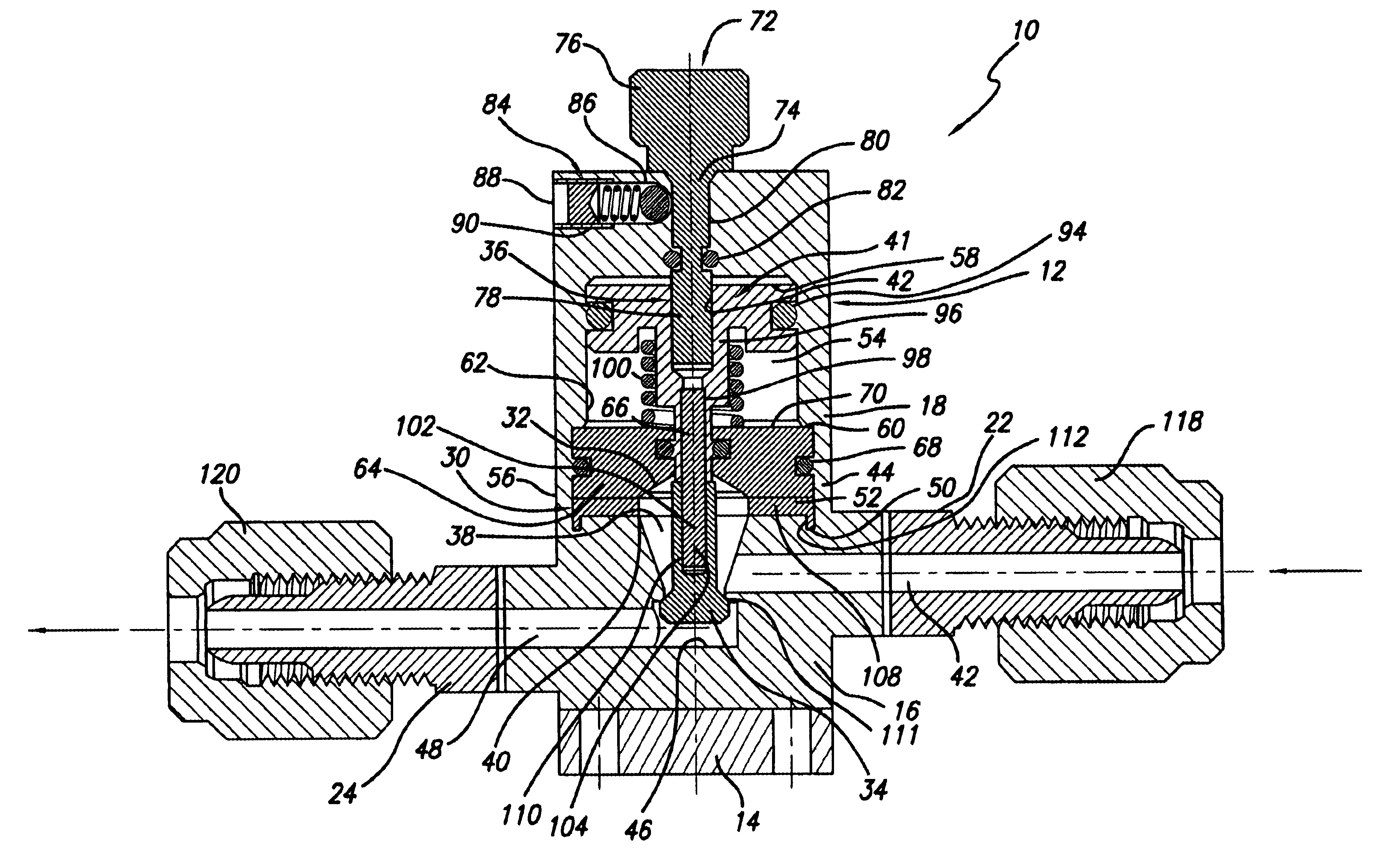
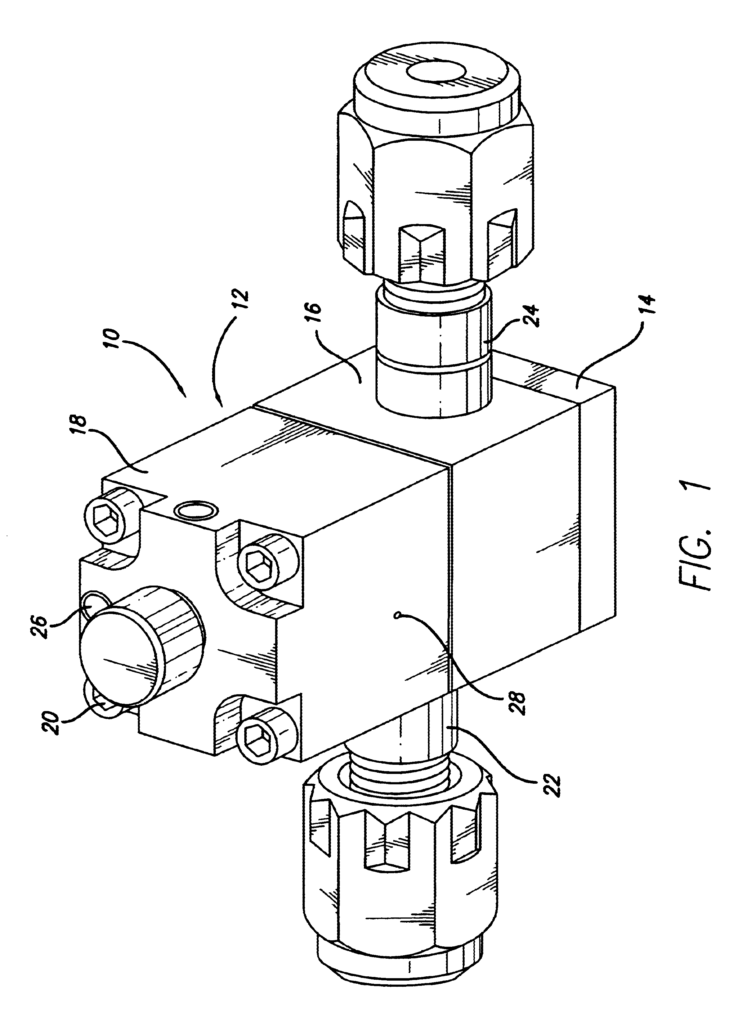
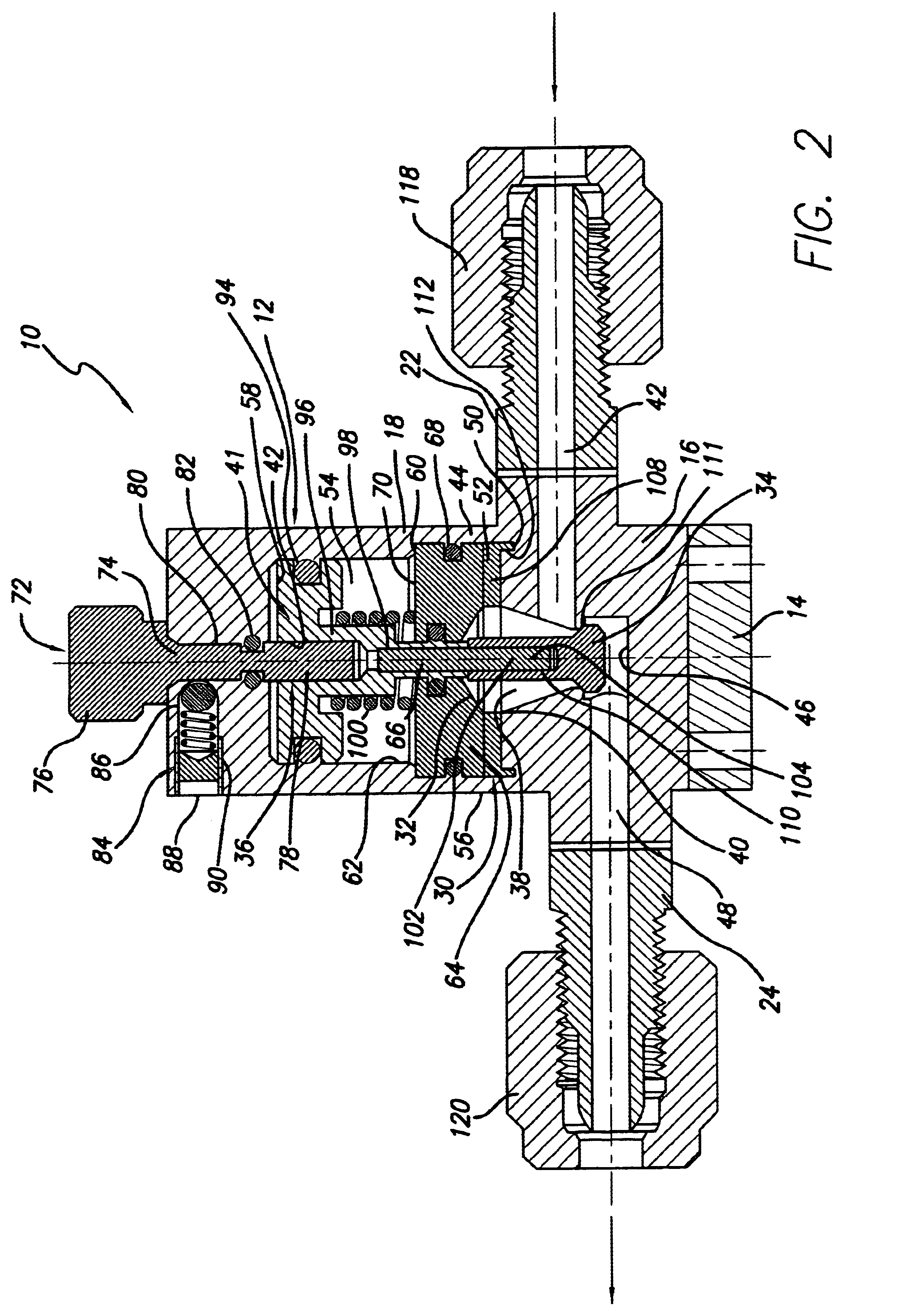
Referring to FIG. 1, a first embodiment dispense valve 10 provided in accordance with practice of the present invention comprises a valve body 12 made up of, moving from the bottom of FIG. 1 upwardly, a base 14, a fluid transport housing (FTH) 16 disposed on top of the base 14, and an actuator housing 18 disposed on top of the FTH 16. Screws 20, or other suitable attachment means, extend through the actuator housing 18 and the FTH 16, and are threaded into the base 14 to attach the actuator housing 18 and FTH 16 thereto.

The FTH 16 includes a fluid inlet port 22 through one of its side walls, and a fluid outlet port 24 through an opposite side wall. In an air- or pneumatically-actuated embodiment of the dispense valve 10, the actuator housing 18 includes an inlet air port 26 and an air outlet port or vent 28 extending through its side wall. The FTH may also be configured having a leak detection port (not shown) extending through one of its side walls to monitor the occurrence of any ...

second embodiment

FIGS. 4 and 5 illustrate a second embodiment dispense valve 200 constructed according to principles of this invention, generally comprising a valve body 202 made up of, moving from the bottom of FIG. 4 upwardly, a base 204, a fluid transport housing (FTH) 206 disposed on top of the base 204, and an actuator housing 208 disposed on top of the FTH 206. Screws 210, or other suitable attachment means, extend through the actuator housing 208 and the FTH 206, and are threaded into the base 204 to attach the actuator housing 208 and FTH 206 thereto.

The FTH 206 includes a fluid inlet port 212 through one of its side walls, and a fluid outlet port 214 through an opposite side wall. In an air- or pneumatically-actuated embodiment of the dispense valve 200, the actuator housing 208 includes an inlet air port 216 and an air outlet port or vent (not shown) extending through its side wall. The FTH may also be configured having a leak detection port (not shown) extending through one of its side wa...


PUM


Abstract

Anti-pumping dispense valves, constructed according to principles of this invention, comprise a fluid transport housing having a fluid inlet passage extending into the housing, a fluid outlet passage extending out of the housing, and a fluid transport chamber disposed within the housing. The fluid transport chamber includes an valve seat. An actuator housing is attached to the fluid transport housing and includes an actuator chamber that is in contact with the fluid transport chambers. A diaphragm/poppet assembly is disposed within the fluid transport chamber and comprises a poppet positioned downstream of the seat for placement against the seat to stop fluid flow through the first fluid transport chamber. An actuator is disposed within the actuator chamber for moving the diaphragm/poppet assembly. Dispense valves of this invention operate to provide a slight vacuum within the fluid flow passageway in the valve to retain or pull back into the valve any nondispensed liquid, thereby eliminating and/or greatly reducing the possibility product contamination via unwanted excess liquid dispensement or dried residual liquid dispensement.

Description

FIELD OF THE INVENTIONThis invention relates to fluid handling valves used for dispensing liquids and, more particularly, to fluid handling valves that are specially designed to repeatably dispense accurate volumes of chemically aggressive and / or chemically pure liquids without degrading or otherwise deleteriously affecting the liquids or the manufactured product.BACKGROUND OF THE INVENTIONFluid handling valves, e.g., fluid dispense valves, are used in applications where the valve internals are subjected to corrosive acidic or caustic liquids, or where the purity of the liquids which flow through the valve must be maintained. An example of such application is the semiconductor manufacturing industry where the process chemical delivered through such a valve must maintain a high degree of chemical purity to avoid contamination that may occur on the microscopic level, and that is know to cause damage to the manufactured product, e.g., a semiconductor wafer.It is also desired, during ce...

Claims


Application Information

Patent Timeline
IPC IPC(8): F16K23/00F16K41/00F16K41/10F16K31/122F16K47/02
CPCF16K41/103F16K23/00
Inventor KINGSFORD, KENJI A.FREGOSO, MARIOSAVARD, RAYMOND T.
Owner SAINT GOBAIN PERFORMANCE PLASTICS CORP
Why Eureka
Try Eureka