Hose clamping structure

a technology of hose clamping and sleeve member, which is applied in the direction of hose connection, pipe connection arrangement, mechanical apparatus, etc., can solve the problems of unnecessary cost of adhesive agent and coating process, and achieve the effect of reducing the space occupied by the hose clamping structure, high pressure resistance, and reducing the length of the portion to be tightened with the sleeve member

Inactive Publication Date: 2005-01-04
SUMITOMO RIKO CO LTD
View PDF13 Cites 4 Cited by
  • Summary
  • Abstract
  • Description
  • Claims
  • Application Information

AI Technical Summary

Benefits of technology

In the present invention, the sleeve member mounted to the outer surface of the rubber hose insertedly fitted to the metal pipe and extending over the entire length of the inserting end portion of the metal pipe is tightened in a two-stage tightening operation where the sleeve member is tightened at two portions apart from each other in an axial direction. The first tightening portion at the leading end side of the inserting end portion has an axial length larger than the second tightening portion inwardly located in an axial direction. At the same time, the first tightening portion extends to reach the leading end of the inserting end portion. With this arrangement, the tightening force of the first tightening portion is exerted to the leading end side of the rubber hose, and the tightening force for clamping the rubber hose to the metal pipe is increased as compared with a conventional two-stage tightening operation. As a result, high pressure-resistance can be assured in a hose clamping structure through which a fluid with high temperature and high pressure is passed. That is, it is possible to prevent the hose from coming off caused by an inner pressure at high temperature (at about 150° C.) which is assumed in an actual use. In addition, since the sleeve member is tightened in a two-stage tightening operation, the length of the portion to be tightened with the sleeve member can be reduced and the space occupied by the hose clamping structure can be reduced accordingly. Further, it is enough to merely form a ring-shaped projecting portion at the leading end of the metal pipe, and such a ring-shaped projecting portion can be formed by bulging process which is simpler as compared with rolling process and is low in cost. In addition, since an adhesive agent is not necessary, costs for an adhesive agent and its coating process are unnecessary. As a result, the cost for the hose connecting structure of the present invention is reduced.
In addition, the first tightening portion may be formed by an integral unit including a tubular portion substantially parallel to an axial direction at an inner end side in an axial direction, and a tapered portion tapered and widened into a conical shape from the tubular portion toward the leading end. Since the first tightening portion includes the tubular portion substantially parallel with the axial direction at an inner end side in an axial direction, and the tapered portion tapered and widened into a conical shape from the tubular portion toward the leading end, there is no fear that the tapered portion crushes the ring-shaped projecting portion formed at the leading end of the metal pipe, and the ring-shaped projecting portion can be properly tightened. Accordingly, the tightening force at the first tightening portion is increased, and as a result, the tightening force of the entire sleeve member for clamping the rubber hose is increased.
Further, the tightening rate of the tapered portion when it compresses the rubber hose between the tapered portion and the ring-shaped projecting portion can be set to 30 to 40 percent. Here, the tightening rate of the sleeve member is a difference in thicknesses before and after the rubber hose is tightened, that is, a rate obtained by dividing the thickness of the rubber hose after the tightening operation by a thickness of a rubber hose before the tightening operation. Since the tightening rate of the tapered portion of the first tightening portion when it compresses the rubber hose against the ring-shaped projecting portion is set to 30 to 40 percent, the tapered portion exhibits proper tightening effect, and the tightening force of the entire sleeve member is increased in conjunction with the tubular portion and the second tightening portion. As a result, high pressure-resistance required in a hose clamping structure through which a fluid with high temperature and high pressure is passed can be sufficiently attained.

Problems solved by technology

In addition, since an adhesive agent is not necessary, costs for an adhesive agent and its coating process are unnecessary.

Method used


Image

  • Hose clamping structure
  • Hose clamping structure

Examples


Embodiment Construction

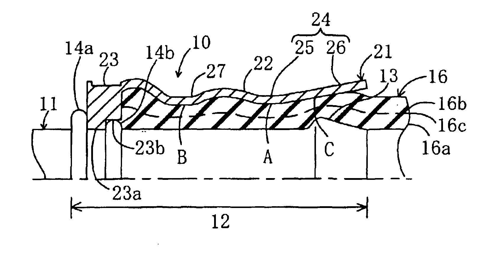
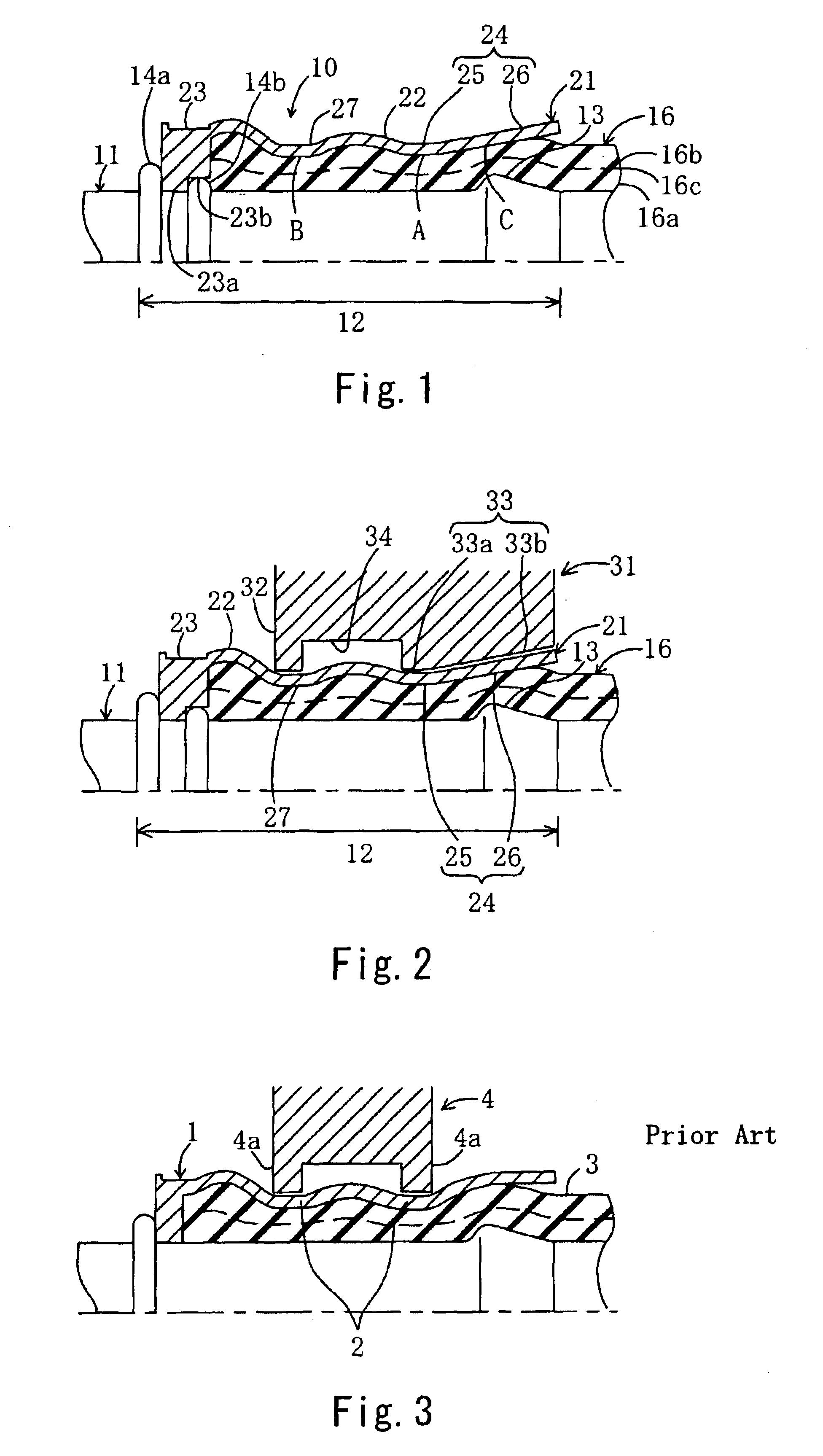
Hereinafter, an embodiment of the present invention will be described by way of drawings. FIG. 1 is a cross-sectional view schematically showing an upper half of a hose clamping structure 10 according to this embodiment, for use in connecting a metal pipe with an oil hose which connects an automatic transmission with a radiator in an automobile. The hose clamping structure 10 includes; a metal pipe 11 which is formed with an inserting end portion 12 extending straightly in an axial direction at one end, a ring-shaped projecting portion 13 formed at the leading end of the inserting end portion 12, and positioning projections 14a, 14b at an inner end in an axial direction: a rubber hose 16 which is insertedly fitted over the entire outer surface of the inserting end portion 12 by press-fitting and is secured thereto in an unbonded manner; and a tubular sleeve member 21 which is mounted to an outer surface of the rubber hose 16 so as to extend substantially over the entire length of th...


PUM

PropertyMeasurementUnit
temperatureaaaaaaaaaa
pressureaaaaaaaaaa
lengthaaaaaaaaaa

Abstract

A hose clamping structure 10 includes: a metal pipe 11 having an inserting end portion 12 straightly extending in an axial direction at one end and having a ring-shaped projecting portion 13 at a leading end of the inserting end portion 12; a rubber hose 16 insertedly fitted to the entire outer surface of the inserting end portion by press-fitting and secured thereto in an unbonded manner; and a tubular sleeve member 21 mounted to the outer surface of the rubber hose and extending over the substantially full length of the inserting end portion, and tightened from outside so as to clamp the rubber hose. The sleeve member includes a second tightening portion 27 and a first tightening portion 24 apart from each other in an axial direction. The first tightening portion includes a tubular portion 25 substantially parallel with the axial direction at the side of the second tightening portion, and a tapered portion 26 tapered and widened into a conical shape from the tubular portion toward the leading end of the inserting end portion.

Description

BACKGROUND OF THE INVENTIONThe present invention relates to a hose clamping structure in which a hose insertedly fitted to the outer surface of an inserting end portion of a metal pipe is clamped and secured to the metal pipe by tightening a sleeve member which is provided to cover the outer surface of the hose.Conventionally, hose clamping structures of this type are classified into those for fuel hose having relatively low pressure-resistance (10 kgf / cm2) and those for power steering hose or freon hose having high pressure-resistance (100 kgf / cm2). In one exemplary hose clamping structure for a fuel hose, an adhesive agent is applied over the outer surface of a metal pipe; the resultant metal pipe and a rubber hose are adhered to each other; and a sleeve member mounted to the outer surface of the hose is tightened to a rubber hose in a flat tightening operation where the tightening section is tightened over a wide area substantially parallel to the axial direction. In another exem...

Claims


Application Information

Patent Timeline
Patent Type & Authority Patents(United States)
IPC IPC(8): F16L33/207F16L33/20
CPCF16L33/2073
Inventor NISHIMURA, MOTOHIDEYUZURIHA, CHIAKI
Owner SUMITOMO RIKO CO LTD
Why Eureka
Try Eureka