Liquid crystal display device with column spacers

a liquid crystal display and column spacer technology, applied in non-linear optics, instruments, optics, etc., can solve the problems of low hardness of plastic spacers, easy deformation, and failure to evenly disperse lc injected between tft substrates, etc., to achieve uniform cell gap, improve picture quality, and high pressure resistance

Inactive Publication Date: 2006-01-17
LG DISPLAY CO LTD
View PDF9 Cites 0 Cited by
  • Summary
  • Abstract
  • Description
  • Claims
  • Application Information

AI Technical Summary

Benefits of technology

[0025]An object of the present invention is to provide an LCD device in which column spacers are formed in a structure in which a high pressure-resistance is obtained and in which an LC can be injected smoothly to maintain a uniform cell gap, thereby improving the picture quality.
[0026]Another object of the present invention is to provide an LCD device in which contact areas between column spacers and a color filter substrate are minimized to enable fine control when a TFT substrate and the color filter substrate are attached to each other.

Problems solved by technology

Compared with a spacer formed of glass, a spacer formed of plastic has low hardness, and is easily deformed by a heavy load.
First, since the column spacers 13 have a rectangular shape, they fail to evenly disperse the LC injected between the TFT substrate 11 and the color filter substrate 11a.
Second, the column spacers 13 have a low pressure-resistance as a result of being arranged in a stripe shape or oblique line shape. To improve the pressure-resistance of the column spacers 13, the amount of space between each of the column spacers 13 may have to be decreased. However, if the amount of space is decreased, bubbles occur in the LC, thereby deteriorating the picture quality.
Finally, rectangularly-shaped column spacers do not generate LC alignment during rubbing, thereby causing a defect in a domain of the LC.

Method used


Image

  • Liquid crystal display device with column spacers
  • Liquid crystal display device with column spacers
  • Liquid crystal display device with column spacers

Examples


Embodiment Construction

[0037]Reference will now be made in detail to the preferred embodiments of the present invention, examples of which are illustrated in the accompanying drawings.

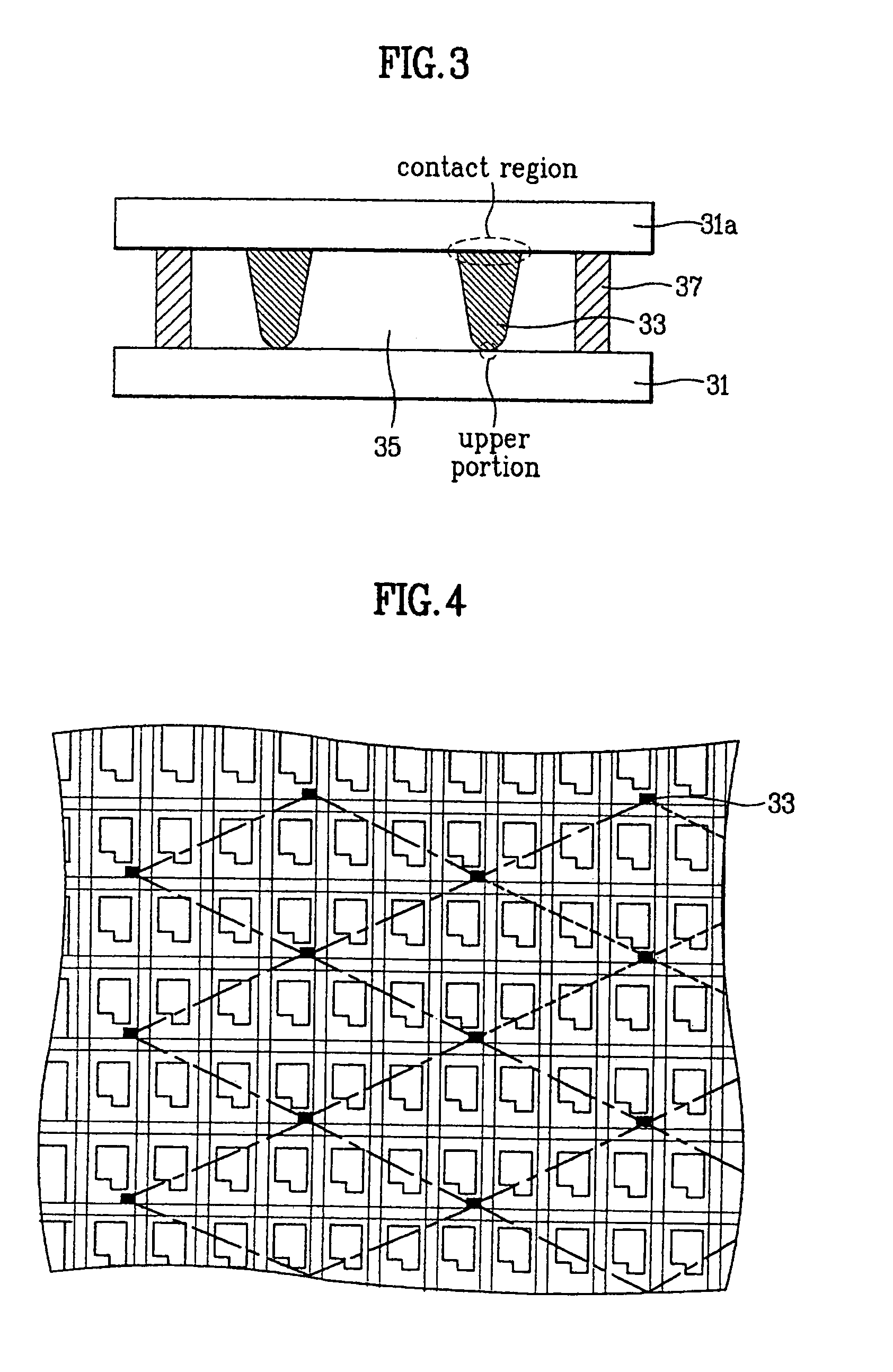
[0038]FIG. 3 illustrates a sectional view of an LCD device according to the present invention.

[0039]As shown in FIG. 3, the LCD device according to the present invention includes a TFT substrate 31 on which a TFT and a pixel electrode are arranged. A color filter substrate 31a is provided on which a color filter pattern and a common electrode are arranged. Column spacers 33 are provided in maintaining a cell gap between the TFT substrate 31 and the color filter substrate 31a, wherein the column spacer 33 are formed on the color filter substrate 31a and an upper (end) portion of the column spacers 33 has a semi-spherical shape. An LC layer 35 is injected between the TFT substrate 31 and the color filter substrate 31a.

[0040]At this time, the TFT substrate 31 and the color filter substrate 31a are attached to each other with a...


PUM

PropertyMeasurementUnit
widthaaaaaaaaaa
lengthaaaaaaaaaa
areaaaaaaaaaaa

Abstract

An LCD device includes a TFT substrate including a plurality of pixels of R, G, and B; a color filter substrate that is spaced apart from the TFT substrate; a plurality of column spacers selectively formed on one of the TFT substrate and the color filter substrate, the column spacers having a semi-spherically-shaped end portion adjacent to the other; and a liquid crystal layer injected between the TFT substrate and the color filter substrate.

Description

[0001]This application claims the benefit of Korean Patent Application No. P2000-80213 filed in Korea on Dec. 22, 2000, which is hereby incorporated by reference.BACKGROUND OF THE INVENTION[0002]1. Field of the Invention[0003]The present invention relates to a liquid crystal display (LCD), and more particularly, to an LCD device having column spacers with a semi-spherical shape in an upper portion.[0004]2. Discussion of the Related Art[0005]Generally, in an LCD, two substrates that are formed apart from each other are attached by forming a liquid crystal (LC) injection hole around them. A liquid crystal (LC) is injected between the two substrates through the LC injection hole, and the two substrates maintain a constant cell gap.[0006]A spacer is generally used to maintain the cell gap between the two substrates. Such a spacer may come in various shapes and be formed of various materials.[0007]The recent trend in thin and light LCD devices has increased the desirability of finely and...

Claims


Application Information

Patent Timeline
Patent Type & Authority Patents(United States)
IPC IPC(8): G02F1/1339
CPCG02F1/13394G02F1/1339
Inventor KANG, DONG HOPARK, JAE SEOKLIM, CHUNG SUNKIM, JIN HO
Owner LG DISPLAY CO LTD
Why Eureka
Try Eureka