Pile-bearing supporting arm type retaining wall

A retaining wall and arm type technology, which is applied in sheet pile walls, soil protection, water conservancy projects, etc., can solve the problem that the bearing capacity of the foundation does not meet the base stress. The problems such as limited force and anti-slip force, the bearing capacity of the foundation does not meet the base stress, etc., can achieve the effect of clear force and force transmission path, high compressive and uplift resistance and horizontal external force bearing capacity, and improve the anti-overturning force.

Pending Publication Date: 2021-06-29
HUNAN PROVINCIAL COMM PLANNING SURVEY & DESIGN INST CO LTD
View PDF0 Cites 0 Cited by
  • Summary
  • Abstract
  • Description
  • Claims
  • Application Information

AI Technical Summary

Problems solved by technology

[0003] Nevertheless, the anti-overturning and anti-sliding forces of the existing cantilever retaining walls are still limited, and it is impossible to solve the problem that the foundation bearing capacity does not meet the base stress without reducing the size of the bottom plate, especially in high fill There are certain limitations in the application of subgrades, soft soil foundations, and subgrades in karst areas, which hinder the promotion and application of this type of retaining wall
[0004] At present, there is no buttress-type retaining wall that can solve the problem that the bearing capacity of the foundation does not meet the foundation stress without increasing the size of the bottom plate, and can improve the overturning and sliding resistance

Method used


Image

  • Pile-bearing supporting arm type retaining wall
  • Pile-bearing supporting arm type retaining wall
  • Pile-bearing supporting arm type retaining wall

Examples


Embodiment

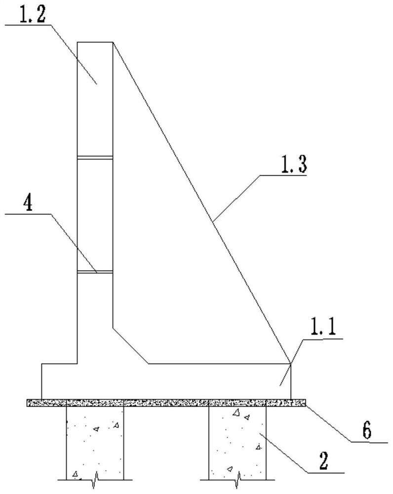
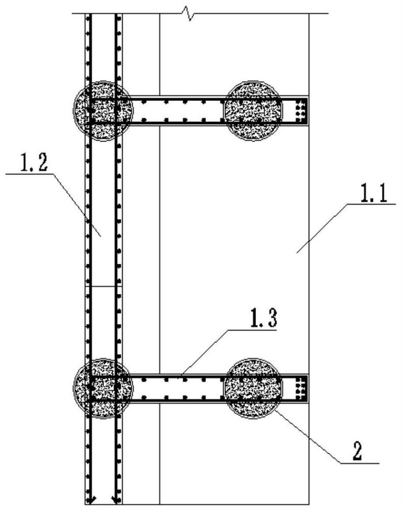
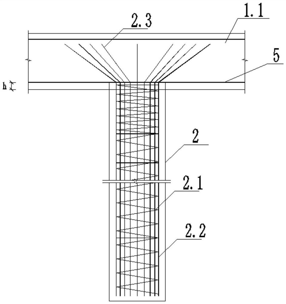
[0035] Such as Figure 1-Figure 3 As shown, the pile-supporting arm-type retaining wall of this embodiment includes a bottom plate 1.1, a vertical arm 1.2 fixed on the bottom plate 1.1, and a rib plate 1.3 for connecting the bottom plate 1.1 and the vertical arm 1.2, and the bottom of the bottom plate 1.1 is fixed. The bored cast-in-place pile 2, and the top of the bored cast-in-place pile 2 extends upwards into the bottom plate 1.1.

[0036] In this embodiment, the bored pile 2 is provided with a spiral stirrup 2.1 and a plurality of vertically arranged main reinforcements 2.2, and the spiral stirrup 2.1 spirally surrounds the main reinforcement 2.2.

[0037] In this embodiment, the upper end of the main reinforcement 2.2 extends upwards to provide an extension section 2.3, and the extension section 2.3 is arranged in the bottom plate 1.1, and the extension section 2.3 is set outwardly by the bored pile 2.

[0038] In this embodiment, the length h from the top of the bored c...


PUM


Abstract

The invention discloses a pile-bearing supporting arm type retaining wall. The pile-bearing supporting arm type retaining wall comprises a bottom plate, a vertical arm fixed to the bottom plate and a rib plate used for connecting the bottom plate with the vertical arm; and a cast-in-situ bored pile is fixedly arranged at the bottom of the bottom plate, and the top of the cast-in-situ bored pile extends upwards into the bottom plate. According to the pile-bearing supporting arm type retaining wall, the cast-in-situ bored pile is only arranged below the bottom plate of the supporting arm type retaining wall, the cast-in-situ bored pile is in rigid connection with the bottom plate, the structure is simple, and the stress and force transmission ways are clear; the cast-in-situ bored pile has high pressure resistance, pulling resistance and horizontal external force bearing capacity; and the bottom plate transmits the dead weight, the upper load, the pressure borne by the vertical arm and other loads to a pile foundation, then the loads are transmitted to foundation soil through the pile foundation, and the purpose of improving the anti-overturning force, the anti-sliding force and the foundation bearing capacity on the premise that the size of the bottom plate is not increased is achieved.

Description

technical field [0001] The invention belongs to the field of protective structures, in particular to a retaining wall. Background technique [0002] At present, the buttress-type retaining wall is usually composed of a base plate, a vertical arm fixed on the base plate, and a rib plate connecting the base plate and the vertical arm. The stability is mainly maintained by the fill soil on the base plate and the rib plate. rice. Due to the small amount of masonry, simple structure and convenient construction, the buttress retaining wall can adapt to the soft foundation and has better stability than the buttress retaining wall. Improvements in anti-overturning and anti-skid forces have been developed rapidly. [0003] Nevertheless, the anti-overturning and anti-sliding forces of the existing cantilever retaining walls are still limited, and it is impossible to solve the problem that the foundation bearing capacity does not meet the base stress without reducing the size of the ...

Claims


Application Information

Patent Timeline
Patent Type & Authority Applications(China)
IPC IPC(8): E02D29/02E02D5/34E02D3/10
CPCE02D3/10E02D5/34E02D29/02E02D2250/0023
Inventor 邱冰欧阳伟强戴旺邓娟红彭立张进华李瑜戴珏向建军郭昊李金光王彦荣邓昆刘扬良赵丰年梁玉刘文婷戴精灵王增强卢永东周荣凯时昊星
Owner HUNAN PROVINCIAL COMM PLANNING SURVEY & DESIGN INST CO LTD
Why Eureka
Try Eureka