Lighting device

Inactive Publication Date: 2005-01-04
MARUMO ELECTRIC
View PDF14 Cites 31 Cited by
  • Summary
  • Abstract
  • Description
  • Claims
  • Application Information

AI Technical Summary

Benefits of technology

In the case that they are constituted as above, since the fixed base plates constituting the holder main body are formed with the finger pushing openings for pressing the gobo pressing plate opposing against each of the fixed base plates in a direction apart from each of the fixed base plate, the gobo pre

Problems solved by technology

However, the adjustment work with such a prior art adjustment mechanism as described above is carried out such that the screw is once loosened, the lens is slid together with the knob, after its position is adjusted, the screw is fastened to fix the lens position, so that there may be present a possibility that the work is troublesome and at the same time the lens position is displaced when the screw is fastened.
In accordance with such a mechanism as above, the adjustment knob is placed at it

Method used


Image

  • Lighting device
  • Lighting device
  • Lighting device

Examples


Embodiment Construction

Referring to the drawings, one example of the preferred embodiment of the present invention will be described as follows.

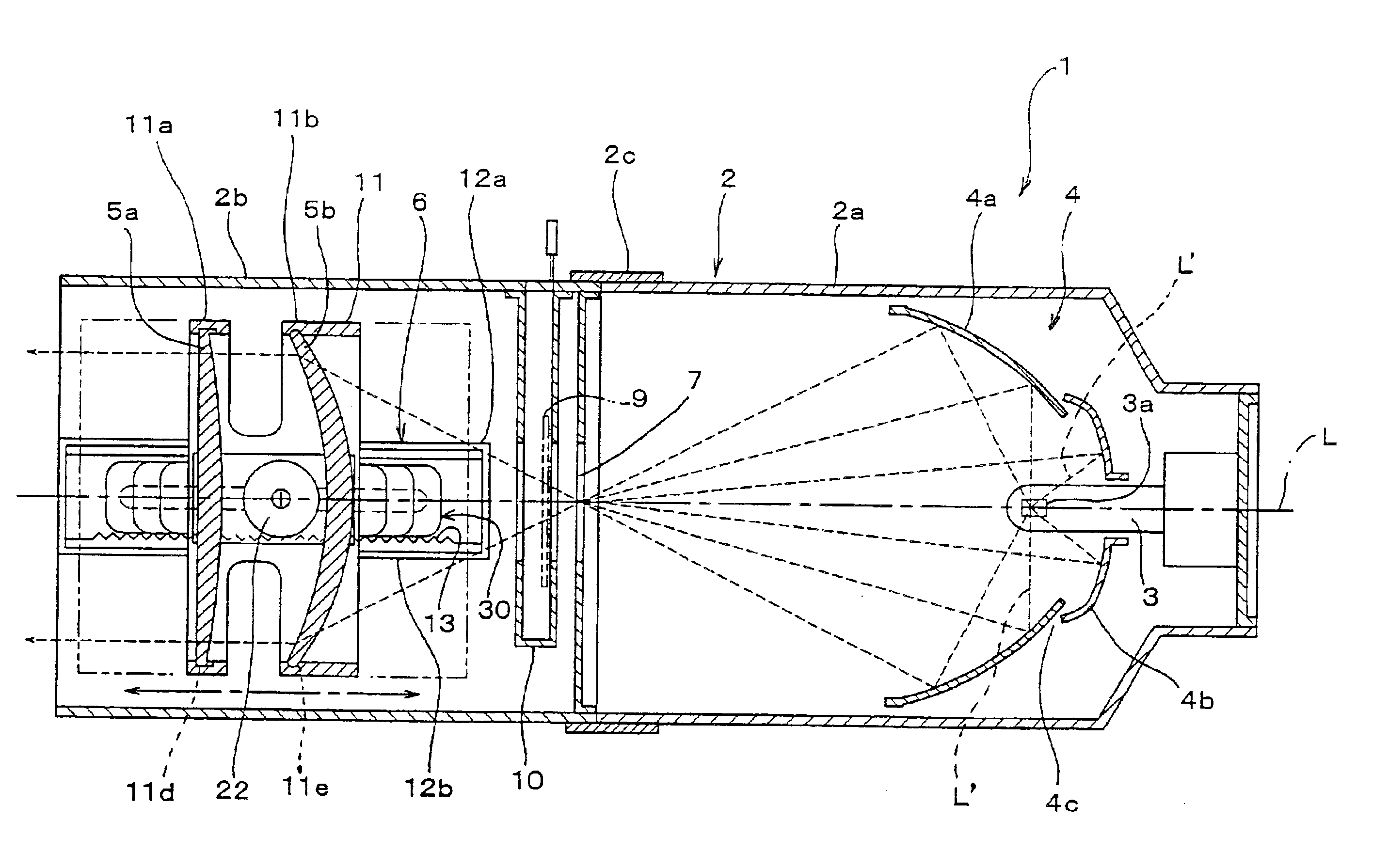
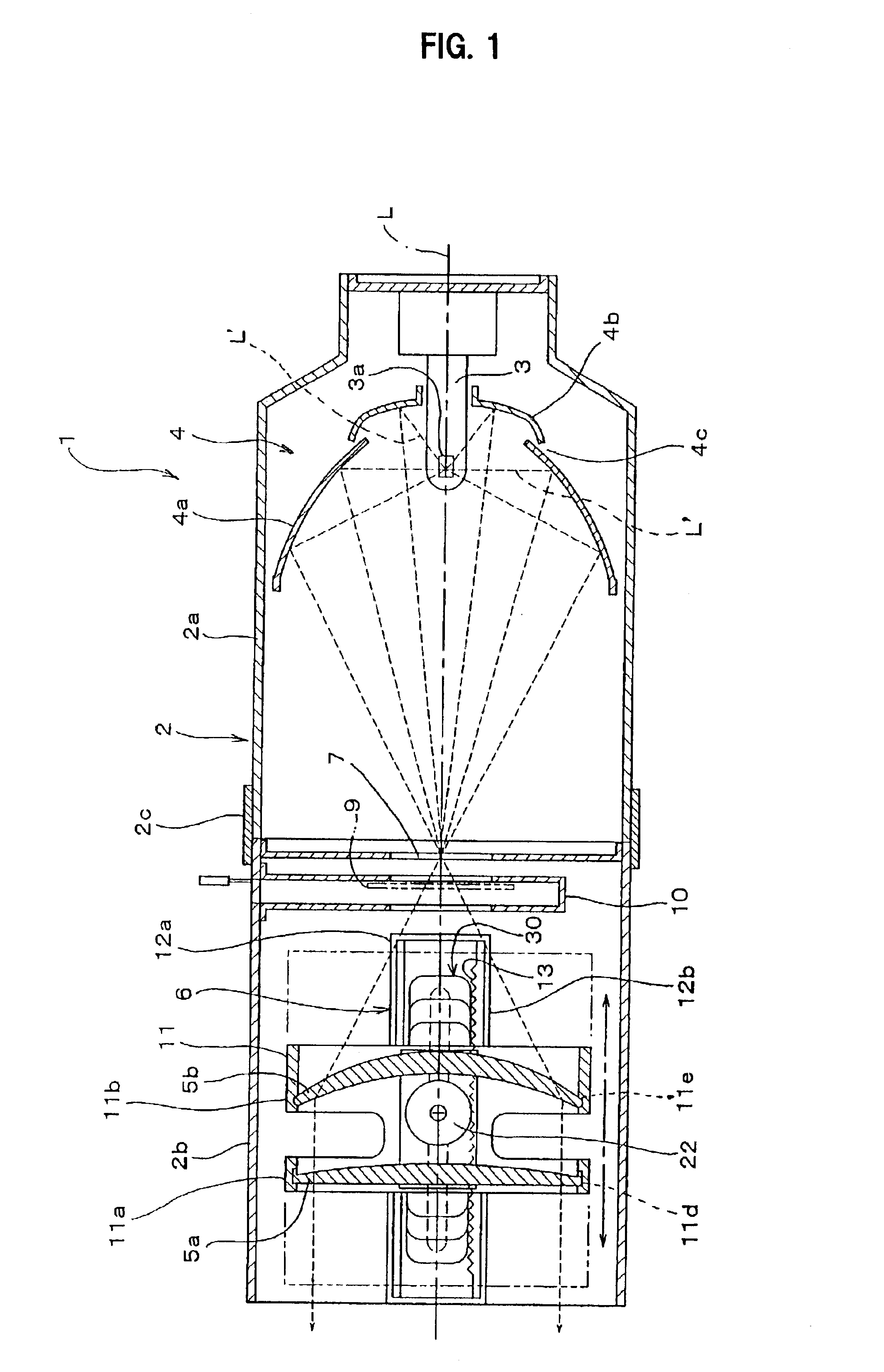
FIG. 1 is a simplified sectional view for showing a schematic configuration of the lighting device 1 of the present invention. In this figure, reference numeral 2 denotes a lighting device, reference numeral 3 denotes a bulb, reference numeral 4 denotes a reflector, reference numerals 5a, 5b denote a lens, respectively, reference numeral 6 denotes a lens position adjustment mechanism for changing a distance between the bulb 3 and the lenses 5a, 5b, reference numeral 7 denotes an aperture, reference numeral 10 denotes a gobo holder slot for use in setting a gobo 9 held by a gobo holder 8 while being held in such a way that it may be freely inserted into or pulled out of it, and L denotes the optical axis.

The lighting device 2 has a structure in which there is provided a shutter frame 2c storing a shutter blade (not shown) for use in shielding light passing through ...


PUM


Abstract

A lighting device includes a reflector that has forward and rearward segments separated by a clearance for cooling, a gobo holder into which gobos of differing sizes can be inserted and held in position, and a lens holder which can be moved forwardly and rearwardly in the lighting device by rotation of a gear which is attached to the lens holder and engages a rack in a slide guide in the lighting device, the gear being moved by a knob located outside the lighting device and which is rotatable with the gear and movable along the lighting device.

Description

TECHNICAL FIELDThis invention relates to a lighting device such as a spotlight or the like used at a stage or a TV studio and the like, for example, in which a bulb, reflector, lens, adjustment mechanism for changing a distance between the bulb and the lens, the desired number of gobos and a holder for holding the gobos under their engaged and held state or the like are arranged at appropriate locations within a housing.More particularly, this invention relates to an improvement of an adjustment mechanism for use in performing a focus adjustment or zoom adjustment lighting device by sliding the lens in a forward or rearward direction along the optical axis, a reflector and a holder for installing gobos (other names: a pattern, a template or the like) used for improving a stage effect in this type of lighting device.BACKGROUND ARTAs the adjustment mechanism for use in performing a focus adjustment or zoom adjustment in this type of lighting device in the prior art, it is well known t...

Claims


Application Information

Patent Timeline
IPC IPC(8): F21S8/00F21S10/00F21V14/06F21V14/00F21V29/00F21Y101/00
CPCF21S10/007F21V14/06F21V13/04F21W2131/406F21V5/008F21V29/004F21V29/83
Inventor TANAKA, TSUNEMICHIISHIZONE, TSUTOMUASAOKU, MASAKIASAKURA, KEIJIRO
Owner MARUMO ELECTRIC
Why Eureka
Try Eureka