
Inlet port for a reciprocating compressor

a reciprocating compressor and compressor technology, applied in machines/engines, liquid fuel engines, positive displacement liquid engines, etc., can solve the problems of hard twisted inlet valves and inconvenient operation, and achieve the effect of preventing deformation and breakage, suppressing self-excited vibration of inlet valves, and improving the suction efficiency of refrigeran

Inactive Publication Date: 2005-01-04
ZEXEL VALEO CLIMATE CONTROL CORP SAITAMA
View PDF12 Cites 4 Cited by
  • Summary
  • Abstract
  • Description
  • Claims
  • Application Information

AI Technical Summary

Benefits of technology

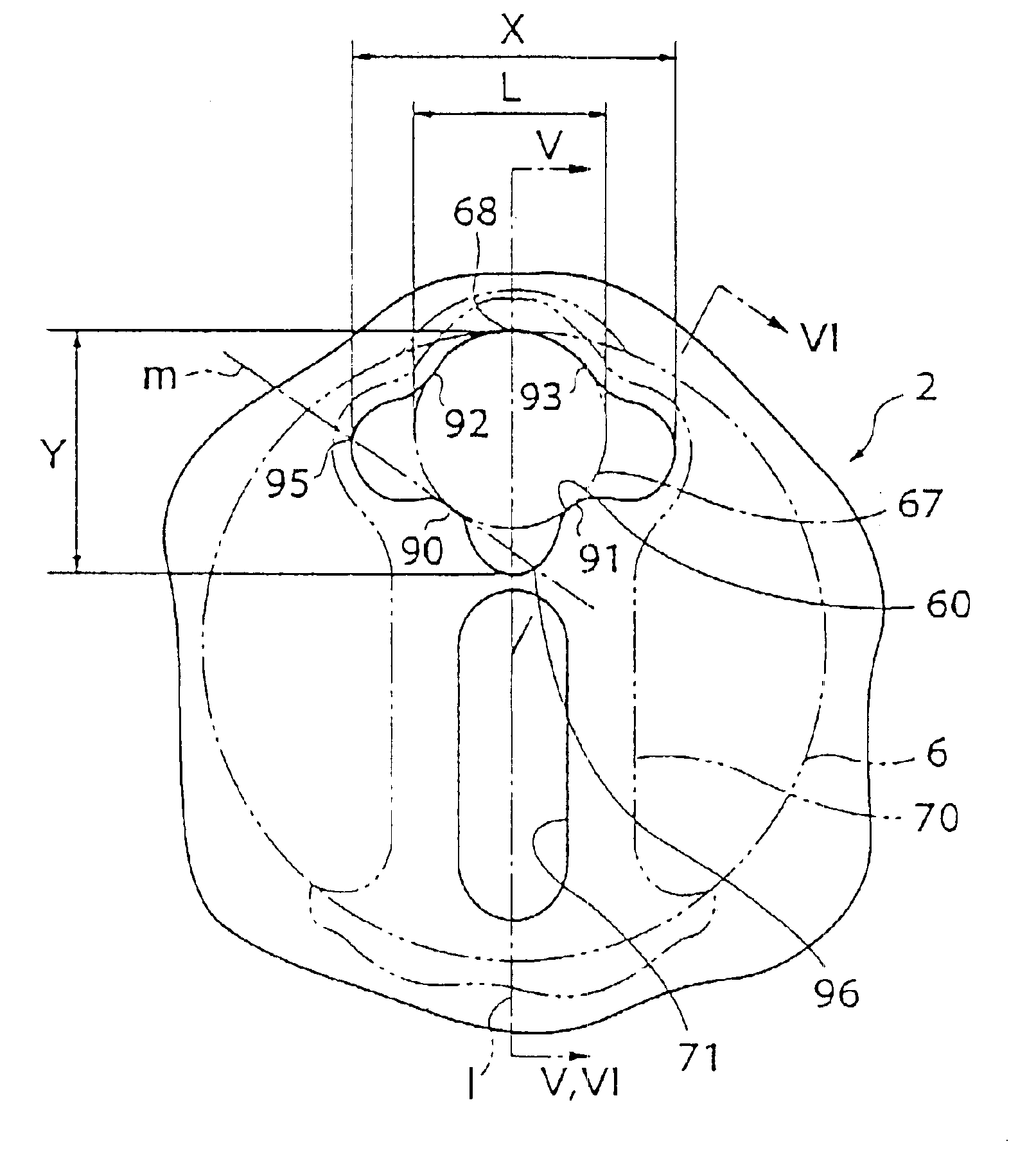
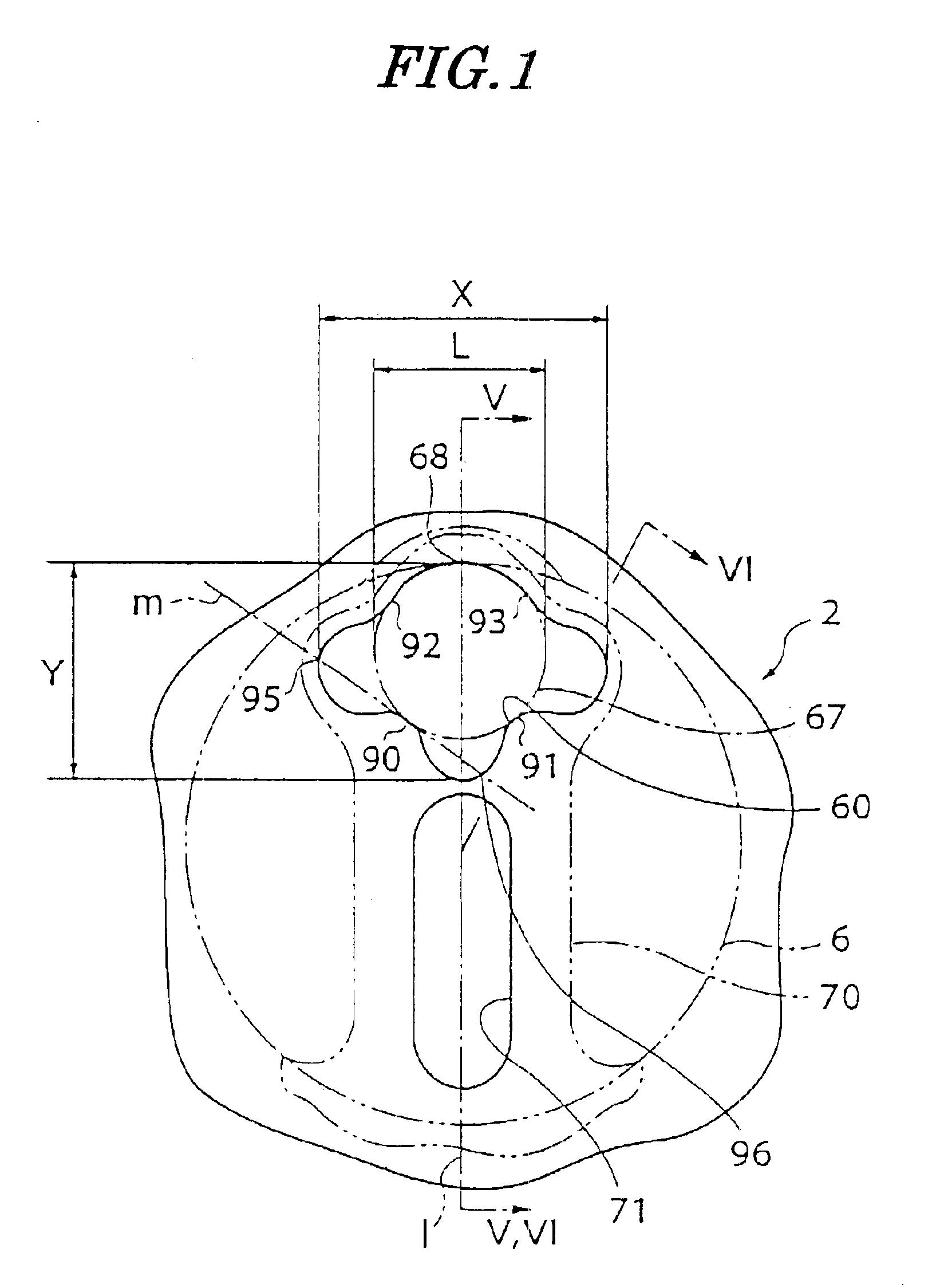
As described above, the shape of the inlet port is non-circular, and a portion of an opening edge of the inlet port protrudes into the inside of the inlet port, with tangential lines drawn from the protruding portion intersecting with the opening end of the inlet port at least two points. Therefore, the refrigerant becomes easy to flow into the compression chamber, and when the refrigerant within the compression chamber is compressed, the inlet valve is supported by the periphery of the inlet port. Further, when the inlet port is opened, the area receiving pressure is large, which increases load of the refrigerant acting on the inlet valve, so that the timing of opening of the inlet valve is not delayed. Therefore, it is possible to prevent deformation or breakage of the inlet valve and resonance of the inlet valve when the refrigerant is compressed, and at the same time, realize the improvement of suction efficiency and suppression of self-excited vibration of the inlet valve, when the refrigerant is drawn in. Further, since a center of an inscribed circle of the inlet port is located on a center line of the inlet valve, when the inlet valve is opened, the inlet valve is hard to be twisted. This makes the inlet valve less prone to being twisted.
As described above, since a diameter of a radial direction of the valve plate is larger than a diameter of the inscribed circle, the flow rate of refrigerant flowing in is increased.

Problems solved by technology

Further, since a center of an inscribed circle of the inlet port is located on a center line of the inlet valve, when the inlet valve is opened, the inlet valve is hard to be twisted.
Further, since a center of the inscribed circle of the inlet port is located on a center line of the inlet valve, when the inlet valve is opened, the inlet valve is hard to be twisted.

Method used


Image

  • Inlet port for a reciprocating compressor
  • Inlet port for a reciprocating compressor
  • Inlet port for a reciprocating compressor

Examples


Embodiment Construction

The invention will now be described in detail with reference to drawings showing preferred embodiments thereof.

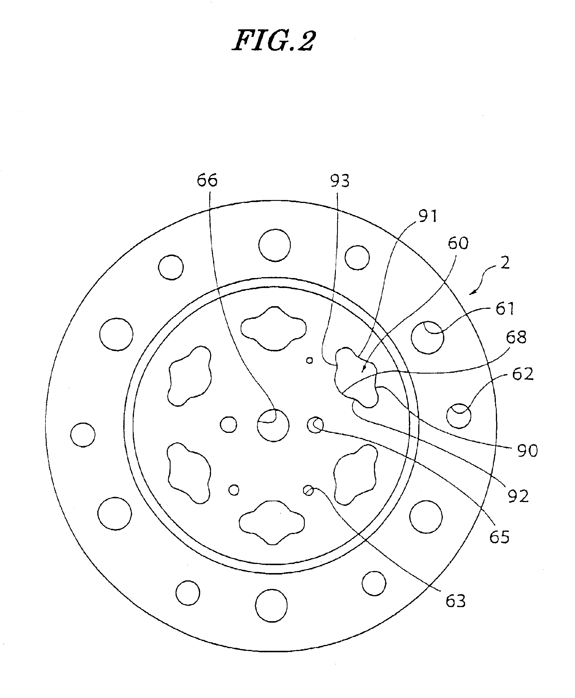
FIG. 4 shows a variable capacity swash plate compressor according to an embodiment of the invention; FIG. 2 is a plan view of a valve plate; FIG. 3 is a plan view of a valve sheet; FIG. 1 is an expanded view of part of FIG. 2; FIG. 5 provide cross-sectional views taken on line V—V of FIG. 1, in which FIG. 5(a) is a view showing a closed state of an inlet valve, and FIG. 5(b) is a view showing an open state of the same; and FIG. 6 is a cross-sectional view taken on line VI—VI of FIG. 1.

This variable capacity swash plate compressor has a cylinder block 1 having one end thereof secured to a rear head (cylinder head)3 via a valve plate 2 and the other end thereof secured to a front head 4.

The cylinder block 1 has a plurality of cylinder bores 6 axially extending therethrough at predetermined circumferential intervals about the shaft 5. Each cylinder bore 6 has a piston 7 slidab...


PUM


Abstract

A reciprocating refrigerant compressor includes a cylinder block having a cylinder bore, and a compression chamber defined within the cylinder bore. A cylinder head has a low-pressure chamber for receiving refrigerant gas to be drawn into the compression chamber, and is coupled to one end face of the cylinder block. A valve plate is arranged between the compression chamber and the low-pressure chamber, and includes an inlet port for guiding the refrigerant from the low-pressure chamber into the compression chamber. An inlet valve opens and closes the inlet port and has an end whose shape is adapted to a shape of the inlet port. The shape of the inlet port is non-circular, and a portion of an opening edge of the inlet port protrudes into the inlet port. Tangential lines drawn from the protruding portions intersect the opening edge of the inlet port at at least two points.

Description

TECHNICAL FIELDThis invention relates to a reciprocating refrigerant compressor and more particularly to a reciprocating refrigerant compressor having a valve plate arranged between a cylinder block and a cylinder head.BACKGROUND ARTConventionally, a type of conventional reciprocating refrigerant compressor has been proposed which includes a cylinder block having a cylinder bore, a piston for linear reciprocating motion within the cylinder bore, a compression chamber defined within the cylinder bore, a cylinder head formed with a suction chamber into which refrigerant gas is received for being drawn into the compression chamber, a valve plate formed with an inlet port for guiding the refrigerant from the suction chamber into the compression chamber, and an inlet valve for opening and closing the refrigerant inlet port.The cylinder head is fixed to one end face of the cylinder blockFIG. 8 is a fragmentary expanded plan view of a valve plate of the conventional reciprocating refrigera...

Claims


Application Information

Patent Timeline
IPC IPC(8): F04B39/10F04B27/10F04B27/08
CPCF04B39/1073F04B27/1009Y10T137/7891
Inventor UNE, KATSUTAKAKUROSAWA, JUETSU
Owner ZEXEL VALEO CLIMATE CONTROL CORP SAITAMA
Learn More