
Rim-driven propulsion pod arrangement

a propulsion pod and rim technology, applied in the direction of rotary propellers, marine propulsion, vessel construction, etc., can solve the problems of wear of the parts supporting the rotating blade sets, and achieve the effect of enhancing water wedge formation and minimizing vibration and wear

Inactive Publication Date: 2005-01-04
ELECTRIC BOAT CORP
View PDF20 Cites 56 Cited by
  • Summary
  • Abstract
  • Description
  • Claims
  • Application Information

AI Technical Summary

Benefits of technology

Another object of the invention is to provide a rim-driven propulsion pod arrangement which minimizes vibration and has improved efficiency.
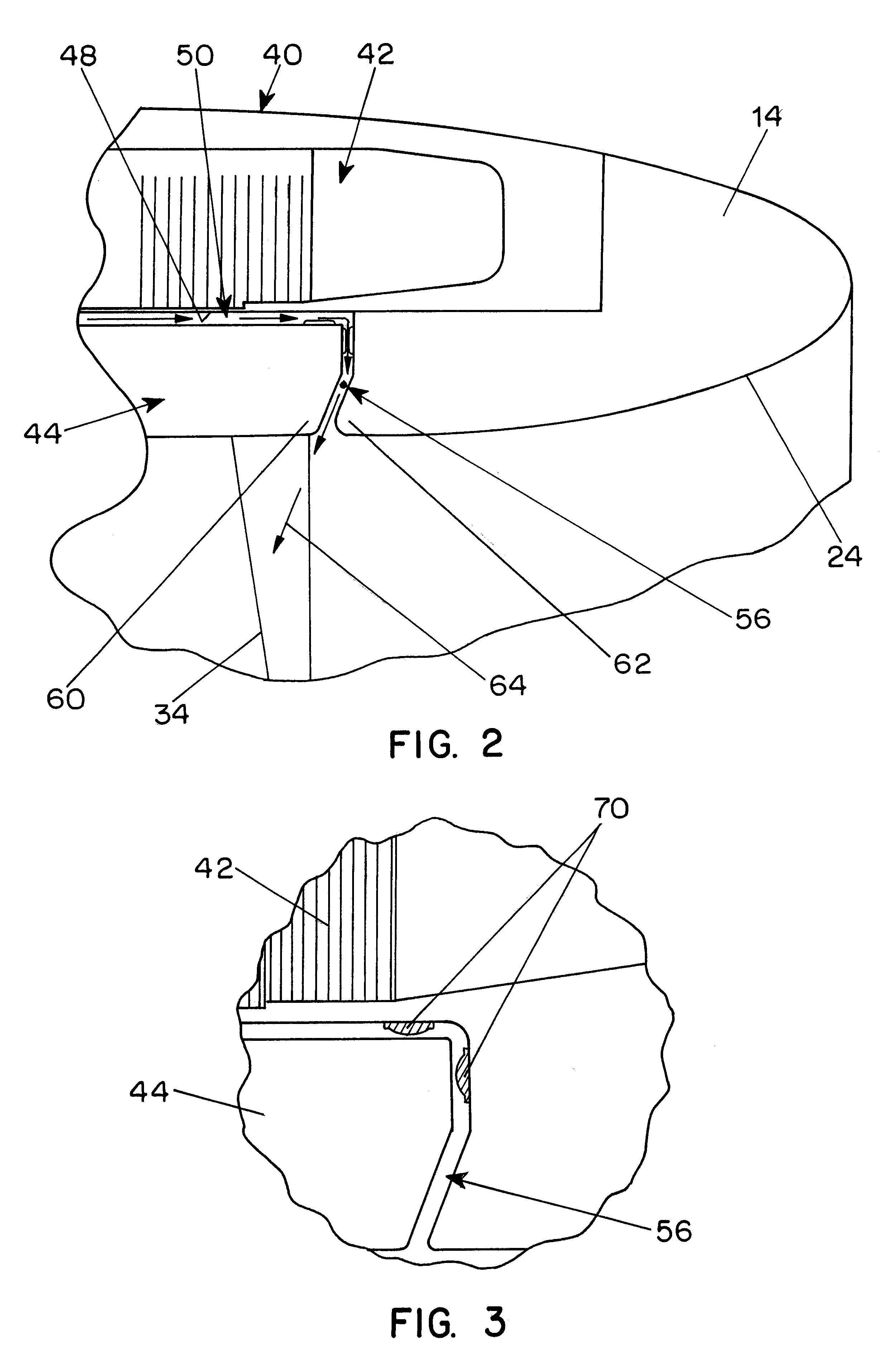
These and other objects of the invention are attained by providing a rim-driven propulsion pod arrangement incorporating a permanent magnet motor with a motor rotor mounted on the rim of a propeller or rotating blade set and surrounded by a stator which is recessed in the surrounding pod portion, permitting the rotor rim to be disposed out of the path of the water passing through the pod. In the preferred embodiment the stator and rotor are canned in composite material to ensure eddy currents are not induced, avoiding efficiency losses. In a preferred embodiment, water is circulated through a path within the pod between adjacent rotor and stator surfaces for cooling and for flushing of any debris from the space between the stator and the rotor. In order to minimize turbulence resulting from return of the circulated water to the low pressure side of the rotating blade set, the return duct is shaped to direct the flow of water at an angle inclined toward the rotating blades rather than radially inward into the flow path. In addition, the propulsion pod includes a stationary blade set located adjacent to and downstream of the rotating blade set which is arranged to cancel swirl in the water ejected by the rotating blades. The design and arrangement of the stationary blade row and the rotating blade row is optimized for efficiency, to reduce cavitation and to minimize induced structural vibration.
In order to assure structural efficiency, ease of wire routing, and even motor cooling, the propulsion pod is preferably supported from a vessel to be propelled by a strut which is attached to the pod adjacent to the plane of the fixed blade set within the pod and spaced from the plane of the rotating blade set. In a preferred embodiment the strut, which carries power and instrumentation lines from the vessel to the pod, has a dry interior with seals between the strut and the pod.
To minimize vibration and wear the rotor is supported by a radial bearing system which provides radial support utilizing radial bearing wear surfaces which in all cases rotate with the rotor to even wear distribution and includes a thrust bearing system which transfers thrust to the stationary structure through thrust bearing surfaces which are machined pad shapes on a solid ring designed to enhance water wedge formation. In addition, soft stationary snubbers or button bearings are located in the pod housing adjacent to the rim of the rotor to limit excursion in the thrust and radial directions which might result from impact, sand or other unusual actions.

Problems solved by technology

Conventional propulsion pods with rim-driven blade sets for marine vessels are subject to vibrations produced by turbulence in the water passing through the pod which may be excessive and may be transmitted to a vessel being propelled and also may be subject to wear of the parts supporting the rotating blade sets.

Method used


Image

  • Rim-driven propulsion pod arrangement
  • Rim-driven propulsion pod arrangement
  • Rim-driven propulsion pod arrangement

Examples


Embodiment Construction

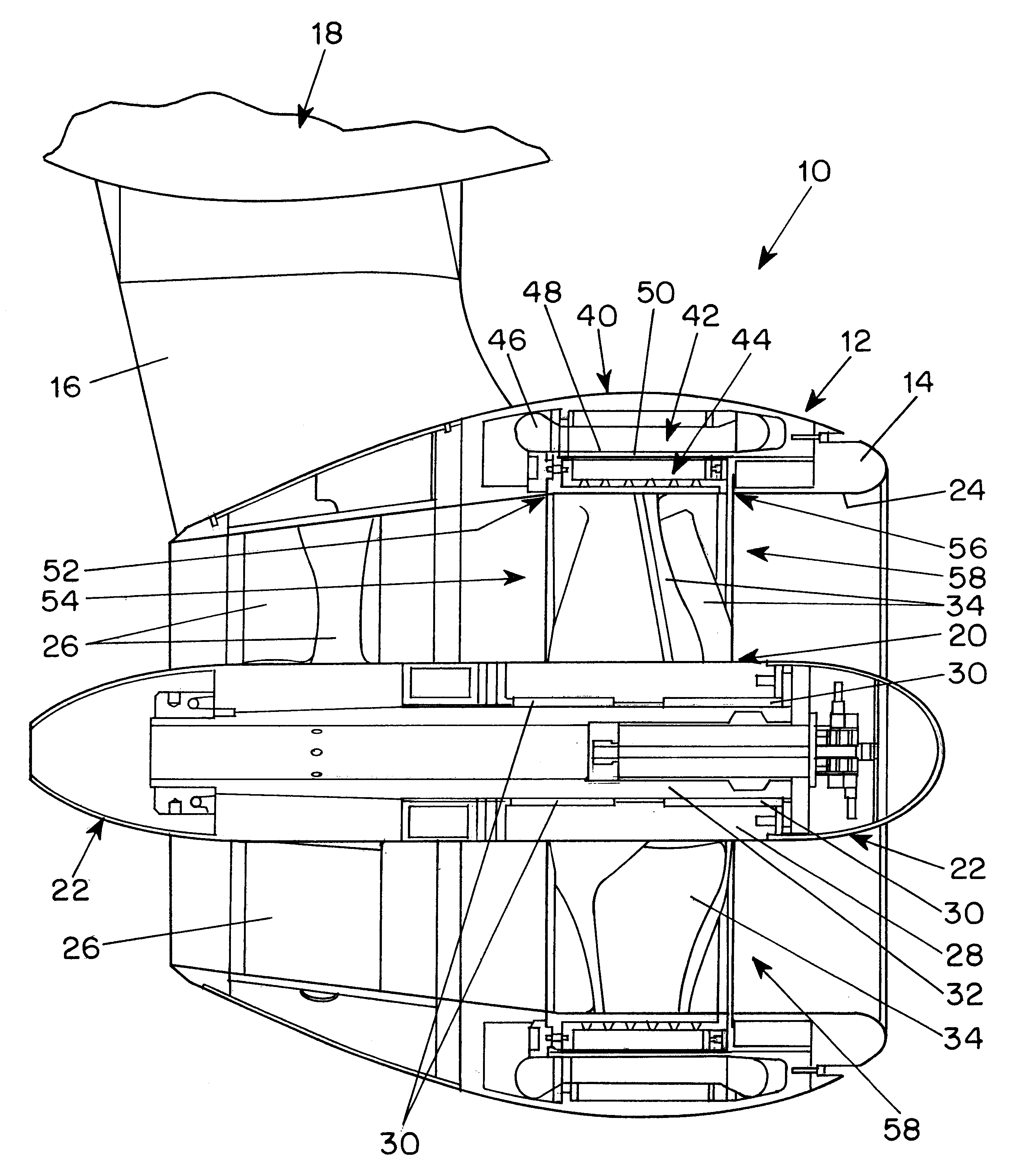
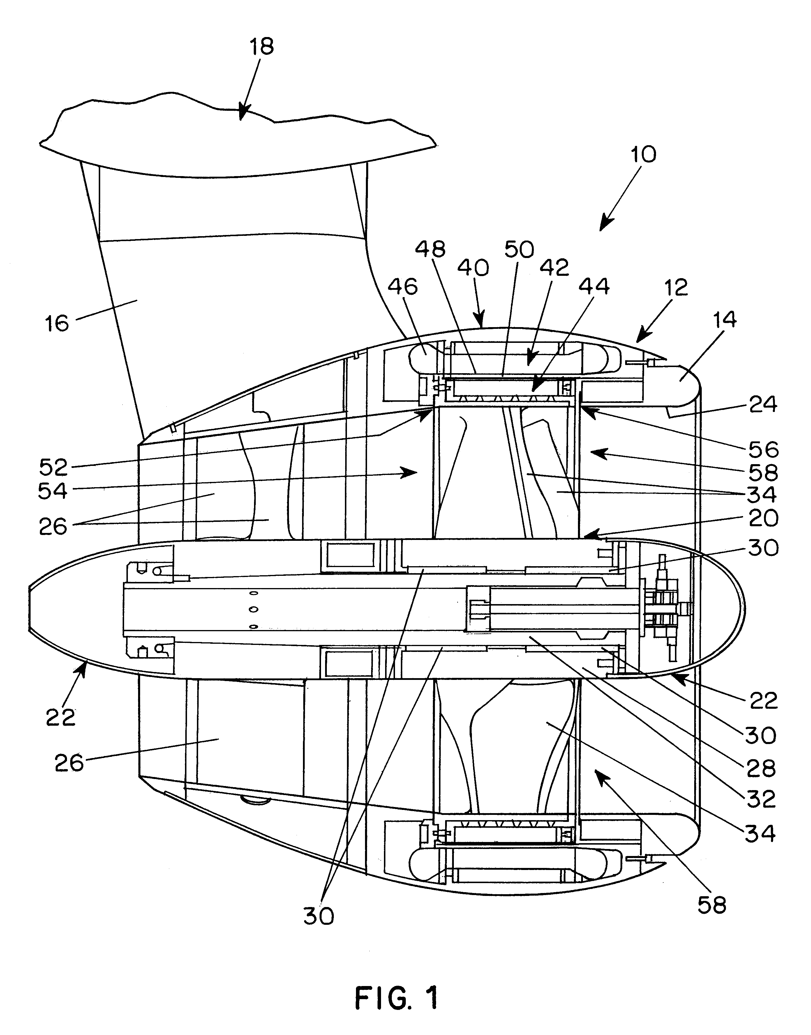
In the typical embodiment of a rim-driven propulsion pod arrangement 10 shown in FIG. 1, a pod 12 has a housing 14 supported by a strut 16 from an adjacent vessel 18 which is to be propelled by the propulsion unit. The pod 12 contains a rotor assembly 20 rotatably supported by a rotor support assembly 22 which is centrally mounted within a central duct 24 in the housing 14 by an array of support members 26 shaped in the form of vanes or blades to guide water emerging from the rotor assembly 20.

The rotor assembly 20 includes a hub 28 containing a plurality of radial bearings 30 rotatably supporting the hub on a central support shaft 32 of the support assembly and an angularly distributed array of blades 34 mounted on the hub and designed and shaped to propel water rearwardly through the housing in an efficient manner during rotation of the rotor assembly. The stationary blades 26 and the rotating blades 34 are designed as a set to cancel the swirl in the water driven by the rotating ...


PUM


Abstract

In the embodiments described in the specification, a rim-driven propulsion pod arrangement has a cylindrical housing with a duct providing a flow path for water and a rotor assembly supported from a central shaft and containing a rotating blade row and driven by a rim drive permanent magnet motor recessed in the housing. An array of vanes downstream from the rotating blade row is arranged to straighten the flow of water emerging from the rotating blade row. Radial bearing members on the rotor have a hardness less than that of the shaft on which the rotor is supported and relatively soft protrusions are provided in the space between the rotor and the housing to limit excursion of the rotor. A thrust bearing has wedges arranged to form a water wedge between facing surfaces of the rotor and the rotor support during rotation of the rotor.

Description

BACKGROUND OF THE INVENTIONThis invention relates to propulsion pods having rim-driven blade sets for propelling marine vessels.Conventional propulsion pods with rim-driven blade sets for marine vessels are subject to vibrations produced by turbulence in the water passing through the pod which may be excessive and may be transmitted to a vessel being propelled and also may be subject to wear of the parts supporting the rotating blade sets.The Veronesi et al. U.S. Pat. No. 5,252,875 discloses a propulsion pod containing a permanent magnet motor driving a rotating blade set and having a rotor rim surrounding the blade set embedded in the surrounding structure so that it is out of the flow path of water through the pod and providing circulation of water through the space between the rotor and the stator from the high pressure side of the rotor to the low pressure side. That arrangement also provides stationary vanes following the rotating blade set to minimize swirling of the water dri...

Claims


Application Information

Patent Timeline
Patent Type & Authority Patents(United States)
IPC IPC(8): B63H23/00B63H23/24B63H1/16B63H1/00
CPCB63H23/24B63H1/16
Inventor VAN DINE, PIETERFRANCO, ALBERTOFORNEY, III, R. SCOTTCHAPMAN, JOHN H.QUADRINI, MICHAEL A.
Owner ELECTRIC BOAT CORP
Learn More