
Capillary electrophoresis method for screening for affinity ligands using a detectable competitive ligand

a competitive ligand and affinity ligand technology, applied in the direction of fluid pressure measurement, liquid/fluent solid measurement, peptide, etc., can solve the problems of unique and difficult challenges of biologically active compounds

Inactive Publication Date: 2005-01-04
NORTHEASTERN UNIV
View PDF9 Cites 13 Cited by
  • Summary
  • Abstract
  • Description
  • Claims
  • Application Information

AI Technical Summary

Benefits of technology

The present invention provides a way of identifying new, biologically active compounds when screening various materials, such as naturally occurring complex biological materials, chemical mixtures, synthetic compounds and other materials, for candidate affinity ligands that bind to target molecules of interest (e.g., molecules involved in a disease). Such candidate ligands have potential regulatory, pharmaceutical, therapeutic, and/or diagnostic applications. The methods o

Problems solved by technology

Developing screens to identify new, biologically active compounds can present unique and difficult challenges, especially when screening complex materials, particularly “complex biological materials”: any material that may have an effect in a biological system.

Method used


Image

  • Capillary electrophoresis method for screening for affinity ligands using a detectable competitive ligand
  • Capillary electrophoresis method for screening for affinity ligands using a detectable competitive ligand

Examples


example 1

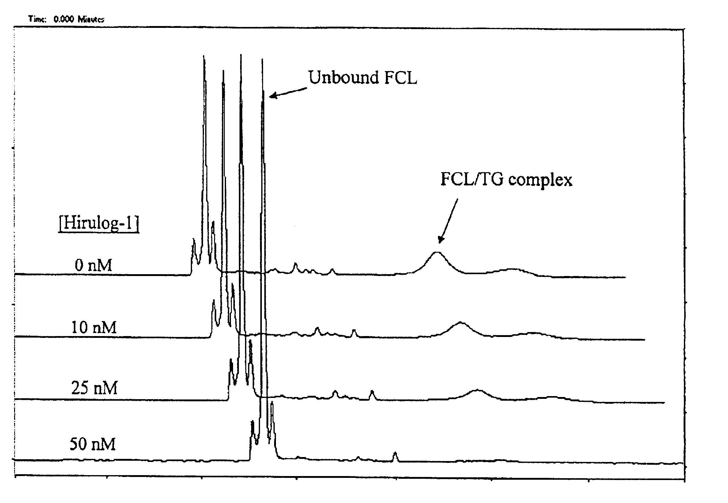
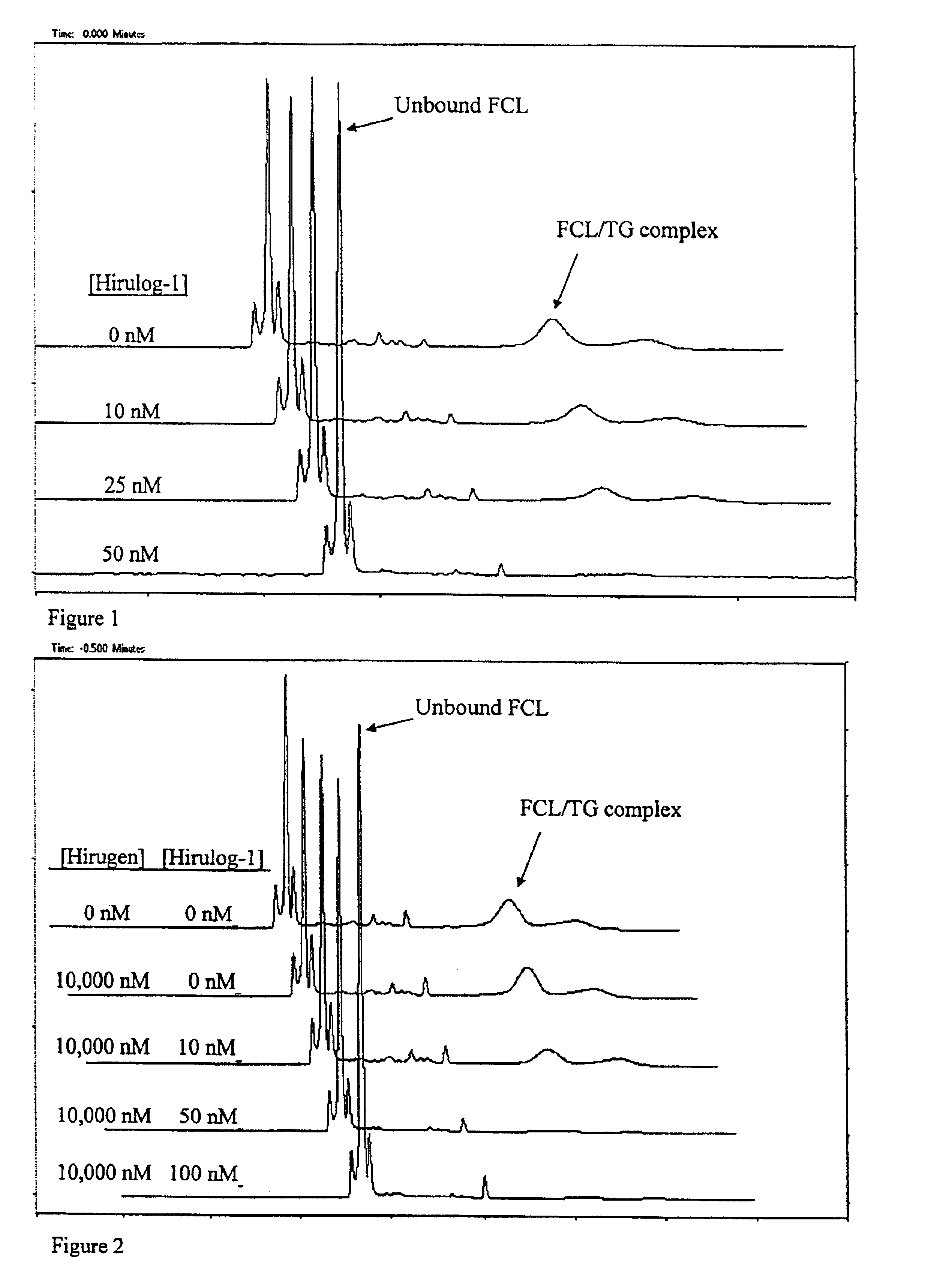
FIG. 1 demonstrates an experiment where 50 nM of a target, the anticoagulant protein, thrombin (TG), is first incubated, prior to CE, for 5 minutes with different concentrations of a test candidate ligand: the tight-binding synthetic ligand, hirulog-1 (D-Phe-Pro-Arg-Pro-(Gly)4-Asn-Gly-Asp-Phe-Glu-Glu-Ile-Pro-Glu-Glu-Tyr-Leu; Kd˜2×10⁻⁹M). Also prepared is 100 nM of a fluorescently labeled, tight-binding competitive ligand, single-stranded (ss) DNA oligonucleotide 5′-fluorescein-GGTTGGTGTGGTTGG-3′ (Kd=3×10⁻⁹ M; hereinafter “FCL”). The mixture of target and candidate ligand (TG / LG) is first injected into the CE instrument for about ten (10) seconds to give a first plug, followed by a 10-second injection of FCL as the second plug.

Voltage of about 20 kV is applied to initiate electrophoresis, and the unbound competitive ligand (FCL) and bound FCL / TG complex peaks are monitored during CE by means of laser-induced fluorescence and a fluorescence detector positioned at a detection point alo...

example 2

FIG. 2 demonstrates an experiment where a tight-binding, test candidate ligand, hirulog-1, is detected even in the presence of high concentrations of a weak-binding test candidate ligand, hirugen (Gly-54-Leu-65 carboxyterminal dodecapeptide of hirudin with sulfated tyrosine; Kd=1.5×10⁻⁷ M). Here the thrombin target (TG) is incubated, prior to CE, for five minutes with samples containing hirugen and hirulog-1 at different concentrations. Each of these target / sample mixtures is subjected to a CE screening run, as follows. A plug of target / sample mixture is pressure-injected into the CE instrument for 10 seconds to give a first-injected plug. A second injection plug of 100 nM FCL is then injected for 10 seconds, and then voltage of about 20 kV is applied to start electrophoresis. The CE migration of the FCL and FCL / TG complex are monitored by way of laser-induced fluorescence. Again, the FCL has a higher electrophoretic mobility than the TG, so that the unbound FCL peak appears before ...


PUM

PropertyMeasurementUnit
Temperatureaaaaaaaaaa
Fractionaaaaaaaaaa

Abstract

The invention relates to a capillary electrophoresis-based method of screening complex materials for any unidentified affinity ligand that binds to a target of interest. The method subjects a plug of a mixture of the target and a complex material sample, and a separate plug of a known, tight-binding competitive ligand, to capillary electrophoresis under conditions optimized to allow mingling of the two plugs during the capillary electrophoresis run. Preferably, migration of the competitive ligand is tracked.

Description

STATEMENT REGARDING FEDERALLY SPONSORED RESEARCH OR DEVELOPMENTNot applicable.BACKGROUND OF THE INVENTIONThis invention relates to the field of capillary electrophoresis-based screening of materials for unidentified compounds that can bind to a target molecule of interest.Developing screens to identify new, biologically active compounds can present unique and difficult challenges, especially when screening complex materials, particularly “complex biological materials”: any material that may have an effect in a biological system. Examples of complex material include, but are not limited to: naturally occurring complex biological materials, such as natural products or extracts; various biological preparations; chemical mixtures; libraries of pure compounds; and synthetic compounds such as combinatorial libraries. Examples of major screening problems include: detecting candidate hit compounds that bind to a target molecule of interest, especially those present at low concentrations in ...

Claims


Application Information

Patent Timeline
IPC IPC(8): G01N33/561G01N33/558G01N27/447
CPCG01N33/561G01N27/447G01N2500/00
Inventor DUNAYEVSKIY, YURIY M.HUGHES, DALLAS E.
Owner NORTHEASTERN UNIV
Learn More