Methods and system for ultrasonic thermographic non-destructive examination for enhanced defect determination

Inactive Publication Date: 2005-01-04
SIEMENS ENERGY INC
View PDF13 Cites 40 Cited by
  • Summary
  • Abstract
  • Description
  • Claims
  • Application Information

AI Technical Summary

Benefits of technology

In view of the foregoing, the present invention advantageously provides methods of enhancing the determination of the presence of a surface breaking or a subsurface defect in an object under test using ultrasonic thermography. The present invention additionally advantageously provides methods and systems that allow qualitative and quantitative information about a defect to be determined and assessed. The present invention also advantageously provides methods and systems that measure dimensions of a defect, which is difficult for other inspection techniques when the defect is located below the surfa

Problems solved by technology

Ultrasonic energy is contactingly transferred at a preselected frequency to the object under test so that the ultrasonic energy causes an incr

Method used


Image

  • Methods and system for ultrasonic thermographic non-destructive examination for enhanced defect determination
  • Methods and system for ultrasonic thermographic non-destructive examination for enhanced defect determination
  • Methods and system for ultrasonic thermographic non-destructive examination for enhanced defect determination

Examples


Embodiment Construction

The present invention will now be described more fully hereinafter with reference to the accompanying drawings, in which preferred embodiments of the invention are shown. This invention may, however, be embodied in many different applications and should not be construed as limited to the illustrated embodiments set forth herein. Rather, these illustrated embodiments are provided so that this disclosure will be thorough and complete, and will fully convey the scope of the invention to those skilled in the art. Like numbers refer to like elements throughout, and prime or double prime notation, if used, generally indicates similar elements in alternative embodiments.

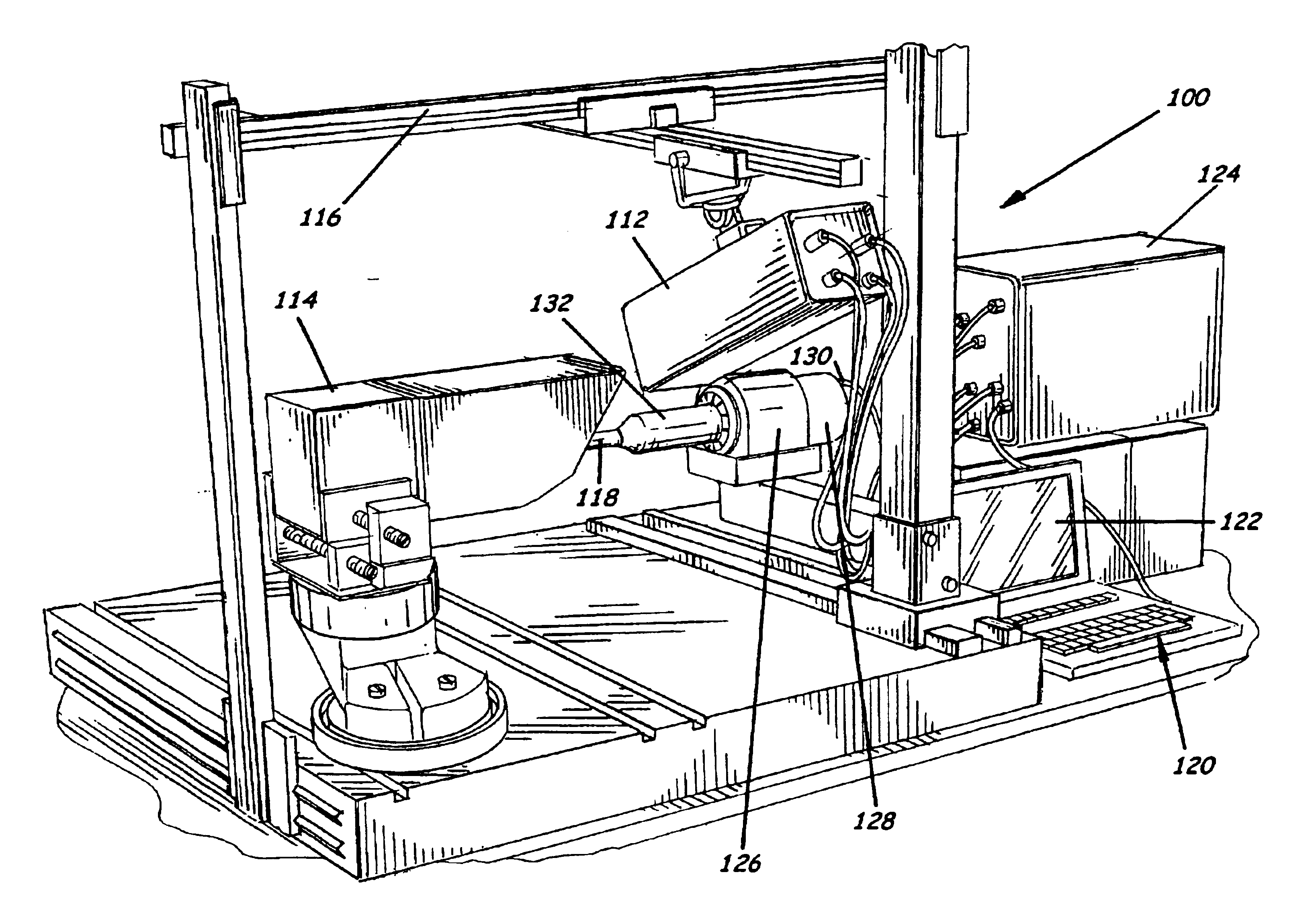
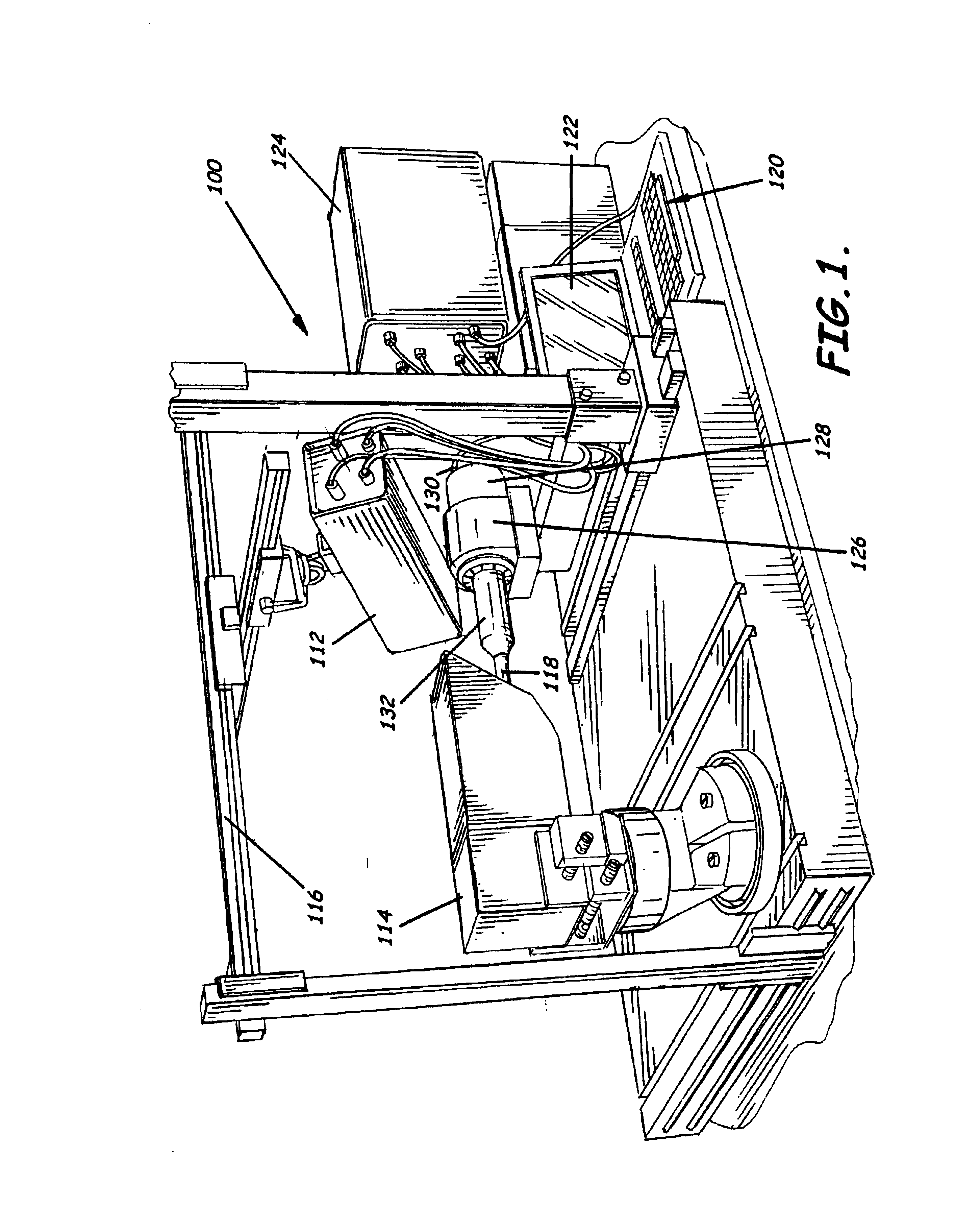
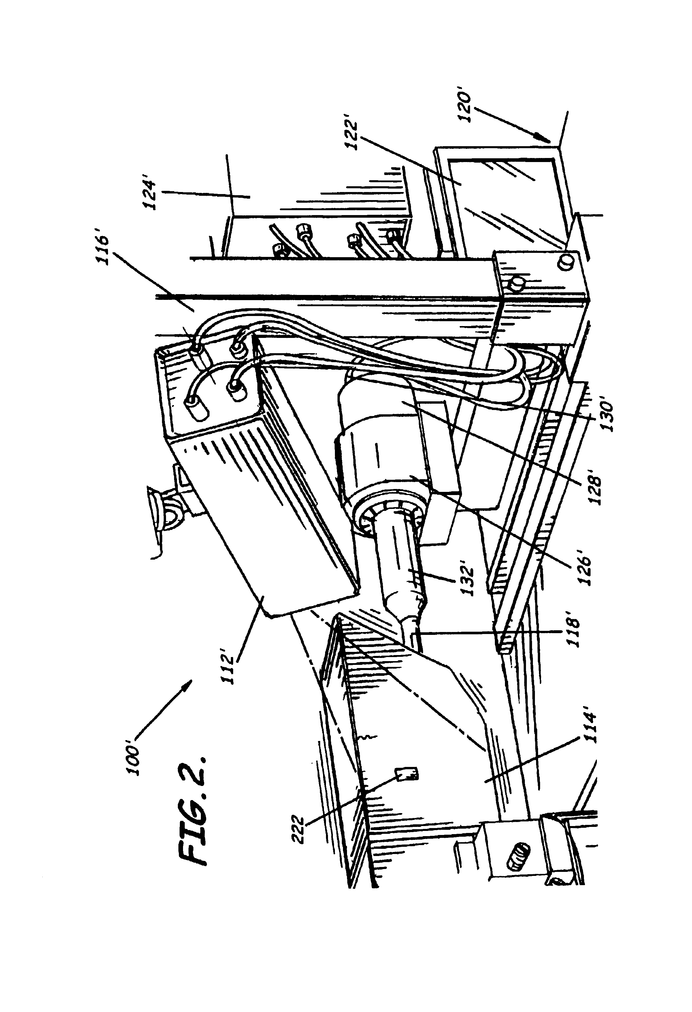
As shown in FIGS. 1-9, the present invention advantageously provides methods of enhancing the determination of the presence of a defect in an object under test. For example, as shown in FIGS. 3 and 5A-5B, a method preferably includes sensing a first test image 514 of at least portions of an object under test 314 with an inf...


PUM


Abstract

A method and system (100) for enhancing the determination of the presence of a surface breaking or subsurface defect with an object (114) under test are provided (FIG. 1). The method can include transferring ultrasonic energy to an object (114) under test and sensing images (514, 514′) of the object (114) under test before and after transferring ultrasonic energy to the object (114) with an infrared thermography camera (112). An increase in temperature gradients in the areas adjacent a defect (516, 516′) is shown in the images (514, 514′) produced by the camera (112), which indicates the presence of the defect (516, 516′). The temperature gradients in the area of the defect (516, 516′) and images of the defect (516, 516′) can be displayed to enable users to determine the temperature gradient and thus the extent of the defect (516, 516′). Digital images (514, 514′) of the before and after transferring ultrasonic energy can be superimposed (514″) to identify and illustrate the defect (516″).

Description

FIELD OF THE INVENTIONThis invention relates to non-destructive testing methods and systems, and, more particularly, methods and systems for enhancing the determination of the presence of a defect in a material.BACKGROUND OF THE INVENTIONIn the power generation industry, various types of non-destructive tests are often used to determine if defects are present in an object. Non-destructive test methods that have been used in the past include liquid penetration, magnetic particle, eddy current, radiography, and ultrasound. These test methods tend to be time consuming and expensive to perform. In recent years, it has become more important to develop inspection techniques which optimize the efficiency of testing by reducing costs and inspection time.One such example of a recently developed inspection method can be found in U.S. Pat. No. 6,236,049 by Thomas, et al. titled “Infrared Imaging of Ultrasonically Excited Subsurface Defects in Materials.” This patent describes the use of infrar...

Claims


Application Information

Patent Timeline
IPC IPC(8): G01N25/72G01N29/34G01N29/24G01N29/04
CPCG01N25/72G01N29/041G01N29/2418G01N29/346G01N29/348G01N29/341G01N2291/02881
Inventor LEWIS, OSCAR O.SCHREINER, THOMAS C.FELIX, MIGUEL A.
Owner SIEMENS ENERGY INC
Why Eureka
Try Eureka