
Operating device for an electrical appliance

a technology for operating devices and electrical appliances, applied in the direction of domestic stoves or ranges, pulse techniques, heating types, etc., can solve the problems of not always being particularly simple in the association of signal-generating signalling means and rotary toggles

Inactive Publication Date: 2005-01-04
E G O ELEKTRO GERAETEBAU GMBH
View PDF10 Cites 43 Cited by
  • Summary
  • Abstract
  • Description
  • Claims
  • Application Information

AI Technical Summary

Benefits of technology

The invention is an operating device for an electrical appliance, such as a cooker, that uses a rotary device for operation. The device has a bearing device that is fixed to the appliance and a rotary device that is fixed to the operating unit. The rotary device is designed to rotate and detect the position of the bearing device using magnetic field sensors. The signals generated by the sensors are processed by control means of the operating device to control the appliance. The device is powered by a contact-free signal transmission, which eliminates the need for separate signalling means on the appliance. The device is simple and cost-effective to manufacture and operate. The technical effects of the invention are that it provides an autarchic operating unit with the signalling means pre-established at all times, avoiding faulty signals and ensuring operational safety and comfort. The device can be used with different types of electrical appliances and can generate signals in response to position changes or rotary operation. The power supply for the device can be provided by the electrical appliance or an external power source. The device can be integrated into the operating unit or a separate control unit. The bearing device can be fixed to the operating unit or the electrical appliance. The device uses magnetic field sensors and a transformer power transmission for contact-free power transmission.

Problems solved by technology

The disadvantage arises that the association of the signal-generating signalling means with the rotary toggle is not always particularly simple and if the association is faulty problems arise.

Method used


Image

  • Operating device for an electrical appliance
  • Operating device for an electrical appliance

Examples


Embodiment Construction

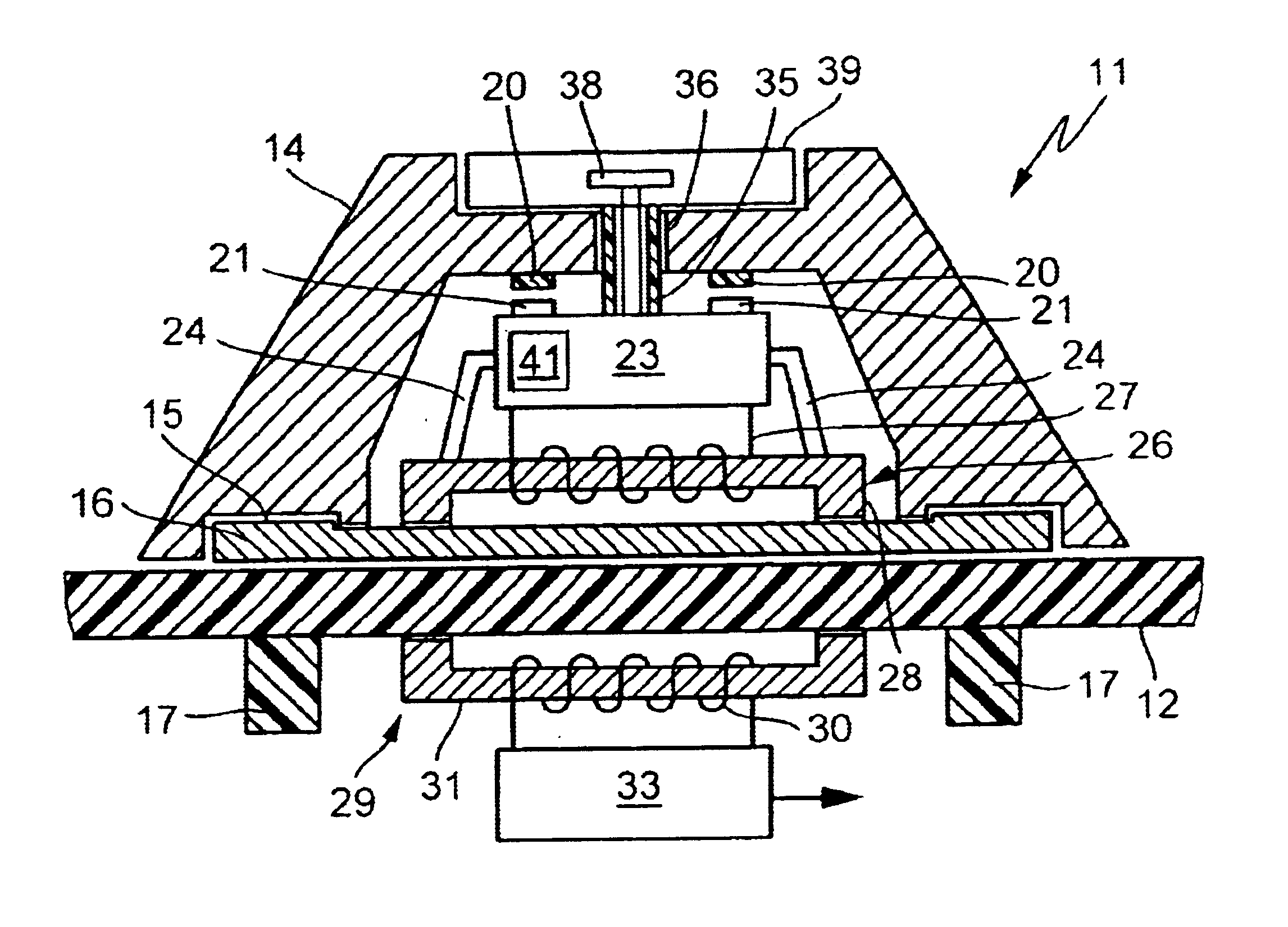
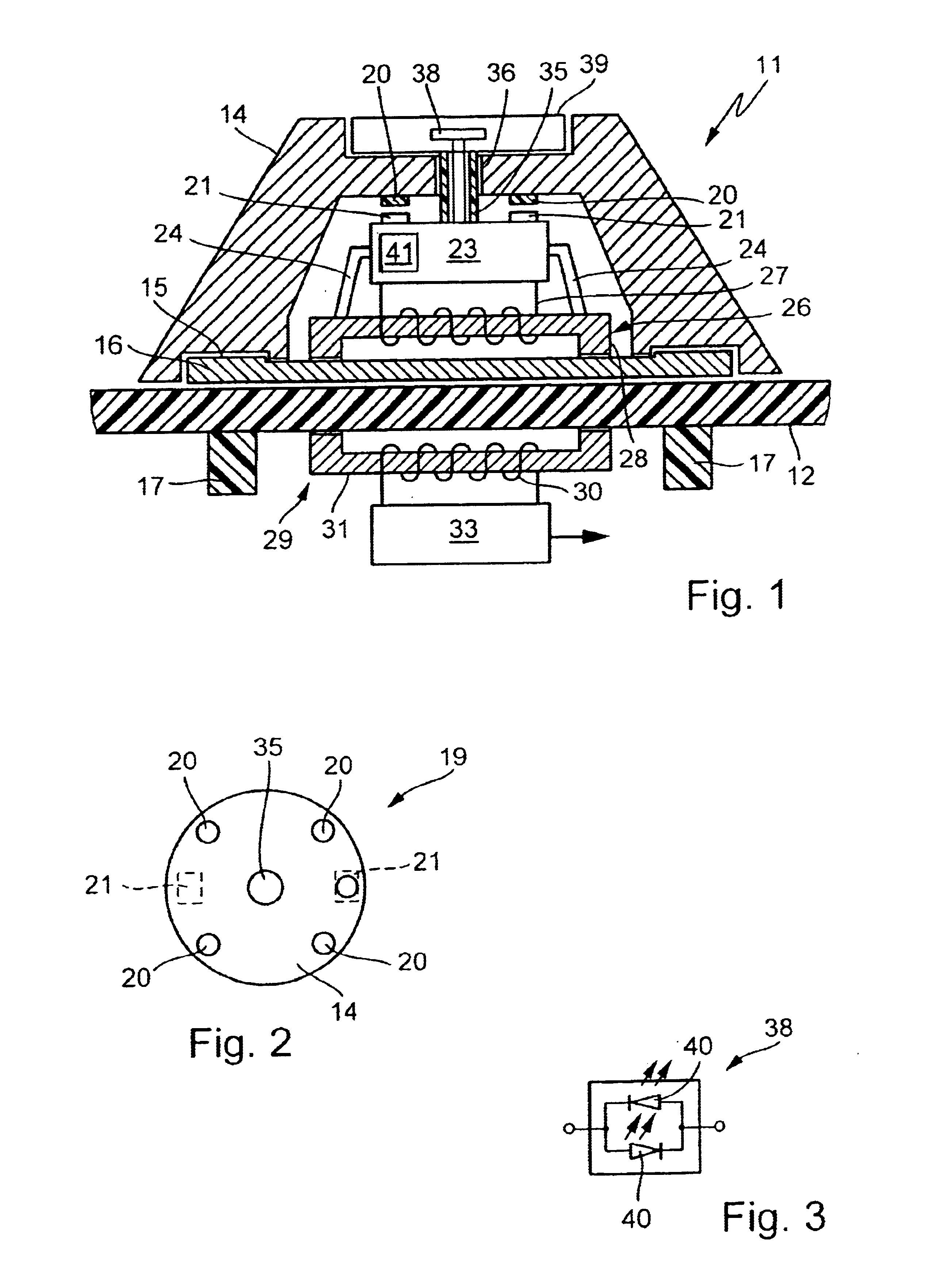
FIG. 1 shows in section an operating unit 11, as can be obtained in an embodiment of the invention. It must be borne in mind that FIGS. 1, 2 and 3 are all to be understood in a diagrammatic manner in order to represent in detail the functionality of an operating unit according to the invention.

The operating unit 11 is placed on a glass ceramic section 12, which forms part of a glass ceramic hob. However, it would also be possible to have a random cover, also made from plastic or as a shield for an electrical appliance.

The operating unit 11 comprises a rotary toggle 14 and is constructed for the rotary operation of the electrical appliance or a not shown functional unit located on said electrical appliance. Such a functional unit can e.g. be a hotplate of a hob. The rotary toggle 14 tapers conically upwards, but this is not absolutely necessary. All that is important is that the rotary toggle forms a type of housing for the functional units or parts housed therein and which will be e...


PUM

PropertyMeasurementUnit
signal transmissionaaaaaaaaaa
magnetic fieldaaaaaaaaaa
electrical signalsaaaaaaaaaa

Abstract

In an embodiment of the invention it is possible to create an operating unit (11) with a rotary toggle (14), which has an integrated bearing device (15) with which the operating unit (11) can be magnetically fixed to a cover (12). The operating unit (11) has a control means (23) with a microprocessor for evaluating magnetic signalling means (19), which detect a rotation of the rotary toggle (14) relative to the bearing device (15). Through a first transformer (26) in the operating unit (11) and a second transformer (29) on the underside of the cover (12), it is possible to have both a signal transmission and a power transmission between the operating unit (11) and the electrical appliance.

Description

FIELD OF APPLICATION AND PRIOR ARTThe invention relates to an operating device for an electrical appliance, preferably an electrical heating appliance such as a cooker.EP 600 780 A1 discloses an operating device for an electric cooker. In this case a rotary device in the form of a rotary toggle is placed in a holder on the surface of an operating unit. In said rotary toggle are provided magnets, which act on reed switches below the surface. In this way it is possible to detect a rotation of the rotary toggle and as a function thereof a switching signal is generated. The disadvantage arises that the association of the signal-generating signalling means with the rotary toggle is not always particularly simple and if the association is faulty problems arise.PROBLEM AND SOLUTIONThe problem of the invention is to provide an operating device of the aforementioned type with which it is possible to avoid the disadvantages of the prior art, particularly with respect to the costs for the enti...

Claims


Application Information

Patent Timeline
Patent Type & Authority Patents(United States)
IPC IPC(8): H03K17/94H03K17/97F24C15/00F24C7/08
CPCH03K17/97F24C7/083
Inventor SCHILLING, WILFRIED
Owner E G O ELEKTRO GERAETEBAU GMBH
Learn More