Power generating system including permanent magnet generator and shunt AC regulator

a permanent magnet generator and power generation system technology, applied in the direction of electric generator control, dynamo-electric converter control, electric generator control, etc., can solve the problems of destroying the generator, and affecting the operation of the generator

Inactive Publication Date: 2005-01-04
HONEYWELL INT INC
View PDF32 Cites 38 Cited by
  • Summary
  • Abstract
  • Description
  • Claims
  • Application Information

AI Technical Summary

Problems solved by technology

Despite their mechanical robustness, permanent magnet generators are not preferred for aircraft generator applications because 1) their output voltage increases essentially proportionally to speed, and 2) they do not survive short circuits applied to their terminals.
Because of their low impedance, short circuit currents in excess of the machine current rating can flow under short circuit applications, causing excessive heat build up in the generator stator windings.
A short in the stator windings can fuse the stator windings and destroy the generator.
If a generator cannot survive the short circuit conditions, it cannot recover upon short circuit removal and it cannot deliver power.
Thus, voltage regulation becomes an issue, since the voltage is proportional to the speed of the rotor.

Method used


Image

  • Power generating system including permanent magnet generator and shunt AC regulator
  • Power generating system including permanent magnet generator and shunt AC regulator
  • Power generating system including permanent magnet generator and shunt AC regulator

Examples


Embodiment Construction

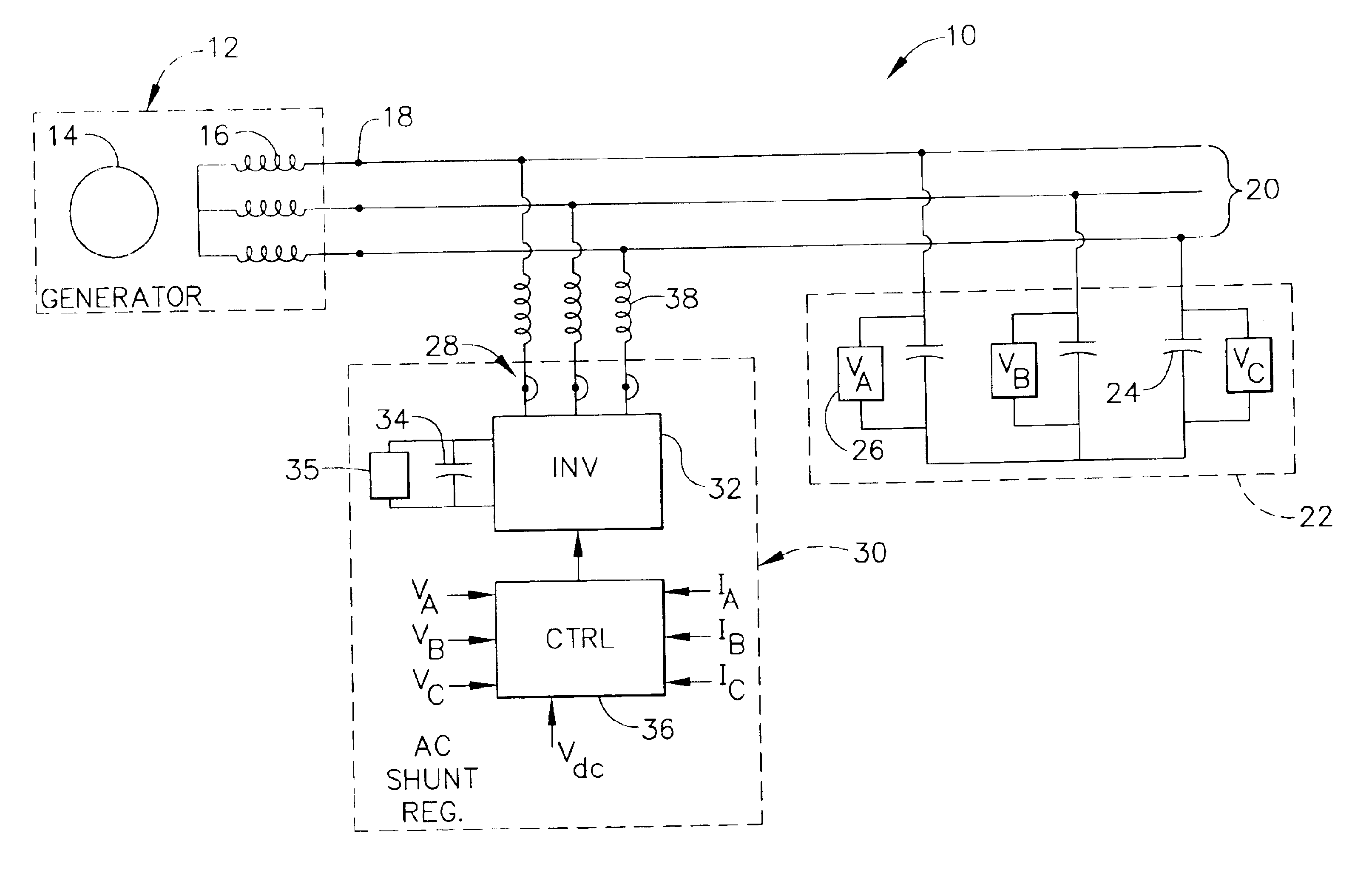
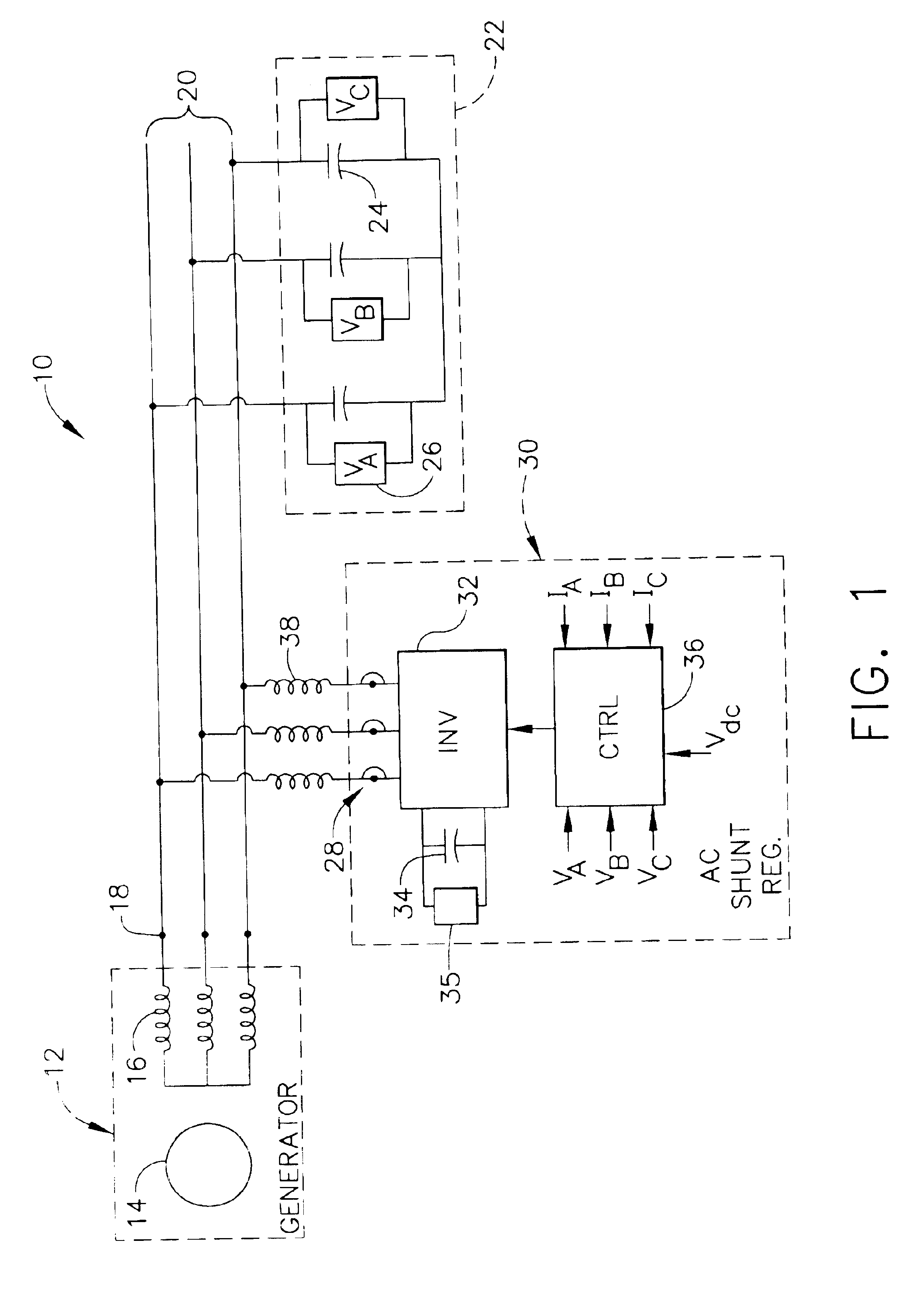
Referring to FIG. 1, an electrical power distribution system 10 includes a permanent magnet electrical generator 12. The generator 12 includes a permanent magnet rotor 14 and three-phase stator windings 16. The stator windings 16 terminate at output terminals 18.

The permanent magnet generator 12 may be designed to sustain rated current (and hence short circuit current) continuously. The generator 12 may be designed such that its stator winding reactance in conjunction with open circuit voltage produces a short circuit current that is essentially the same as the current required to produce rated power. Further, the generator 12 may be designed such that the short circuit current can circulate continuously without causing over-temperature of the windings 16, which in turn would lead to failure of the generator 12. With the generator 12 thermally designed for short circuit current, the short circuit currents will not damage the windings 16, since the thermal ratings under both short ci...


PUM


Abstract

An electrical power distribution system includes permanent magnet generator, and an ac regulator. The ac regulator includes an inverter shunt-connected to the permanent magnet generator, and an inverter control for causing the inverter to regulate voltage at output terminals of the generator by providing reactive power (either leading or lagging) that circulates between the inverter and the generator.

Description

BACKGROUNDThe present invention relates to electrical power generation. More specifically, the present invention relates to a permanent magnet generator and control.Constant voltage, variable frequency (CVVF) aircraft electrical distribution systems are being considered by commercial airframe companies. The CVVF systems would be required to deliver 115 volt, three phase electric power at frequencies varying between approximately 350 Hz, and 760 Hz to on-board electronics such as avionics, vapor cycle systems, and electrically driven hydraulic compressors.A so-called “Two Pole Toothless” permanent magnet generator would be desirable for CVVF systems because of its robust rotor design and a low magnetic spring rate associated with a large air gap. This permanent magnet generator could be driven at prime mover speed (e.g., 24,000 rpm) without an intermediate gear train and constant speed drives. These features would allow the permanent magnet generator to be integrated directly with a ...

Claims


Application Information

Patent Timeline
Patent Type & Authority Patents(United States)
IPC IPC(8): H02J3/18H02P9/00H02P9/02
CPCH02J3/1842H02P9/02H02P2101/30Y02E40/22Y02E40/20
Inventor HUGGETT, COLINKALMAN, GABOR
Owner HONEYWELL INT INC
Why Eureka
Try Eureka