Magnetically coupled antenna range extender

a technology of magnetic coupling and antenna, applied in the field of antennas, can solve the problems of increasing the operating range of the device, unable to reach the asset of interest, and unable to achieve the effect of increasing the operating rang

Inactive Publication Date: 2005-01-04
A C C SYST
View PDF14 Cites 284 Cited by
  • Summary
  • Abstract
  • Description
  • Claims
  • Application Information

AI Technical Summary

Benefits of technology

The antenna range extender of the present invention, including the coil and capacitor thereof, is most preferably located interposed between, and proximate to one of the RF antenna and the electronic device. A most preferable antenna range extender is located proximate to, and interposed substantially upon an axis that is establishable between the RF antenna and a nearby electronic device—but without being directly (electrically) connected to either. As such, the antenna range extender may preferably be positioned proximate to (say 0.5 to 5 centimeters from) the R

Problems solved by technology

For a given application, having to get that close to the asset of interest may be difficult, if not impossible.
However, active transponders generally include a battery, and are larger and more expensive than their passive counterparts.
This results in a significant cost difference between the low cost p

Method used


Image

  • Magnetically coupled antenna range extender
  • Magnetically coupled antenna range extender
  • Magnetically coupled antenna range extender

Examples


Embodiment Construction

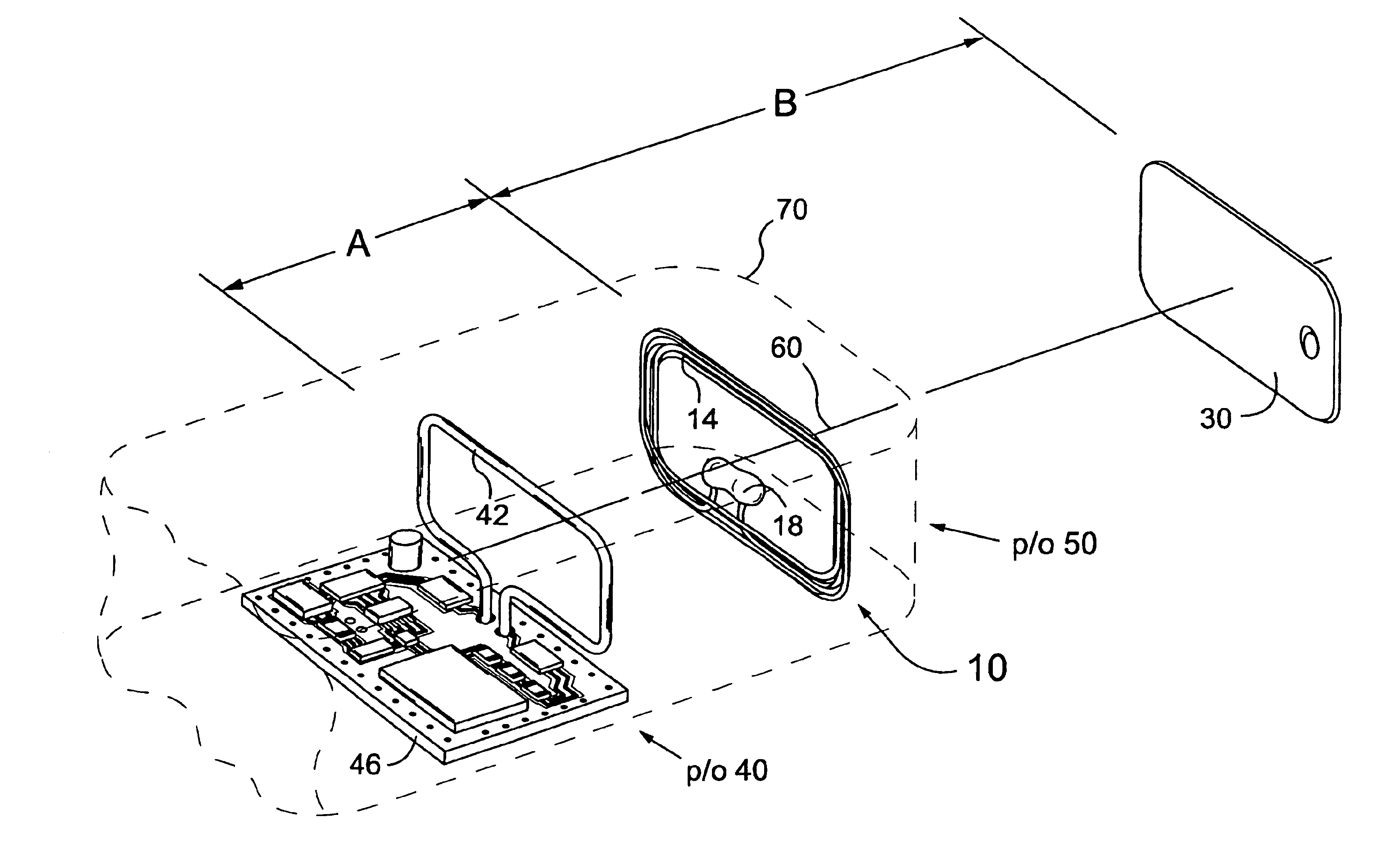
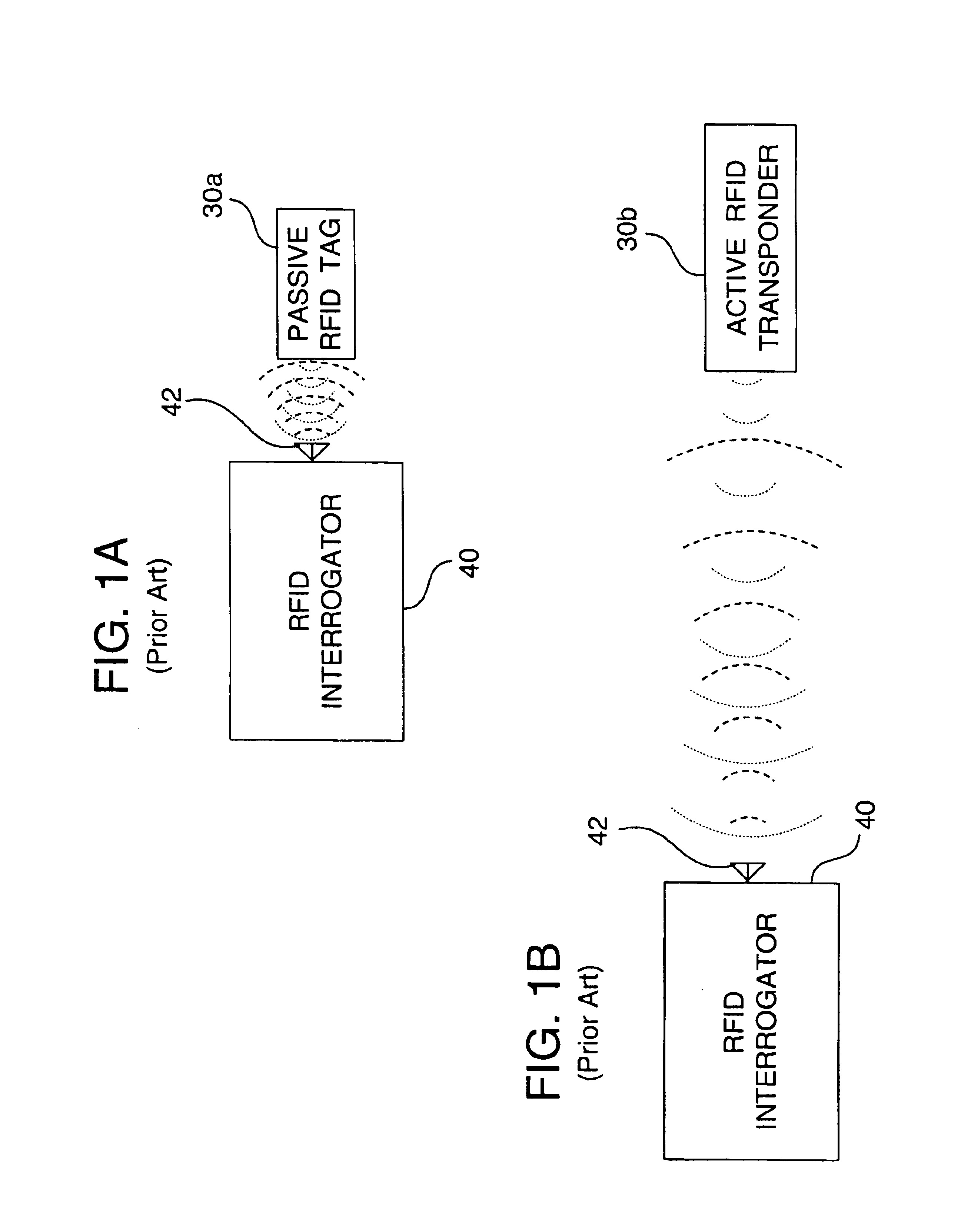
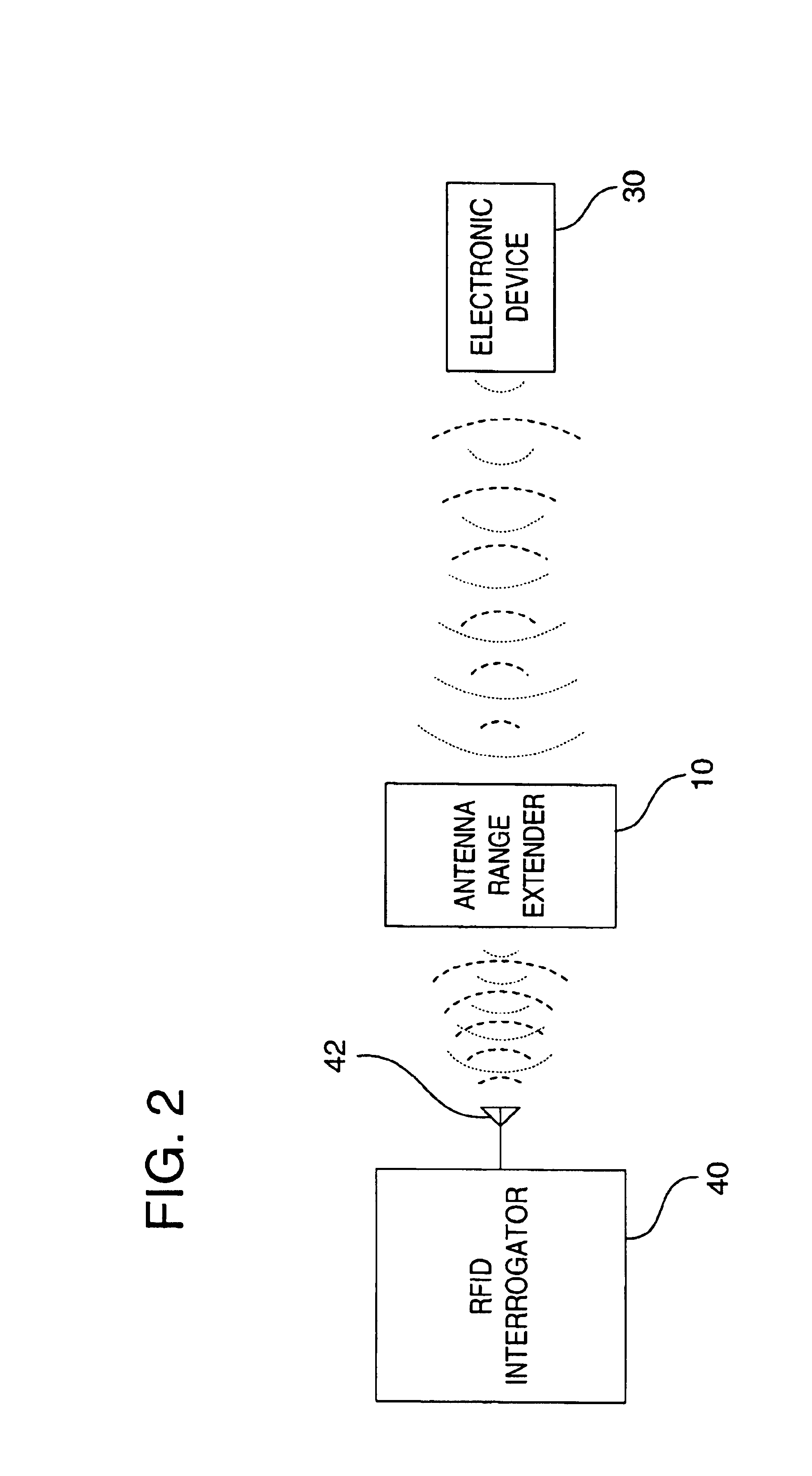
In accordance with the present invention, a magnetically coupled radio frequency (RF) antenna range extender is structured for extending an operating range (or operating distance) between an RF antenna and an electronic device with which information is to be exchanged. Essentially an RF signal is radiated from the RF antenna and received by the electronic device. It may be noted that the RF antenna in a preferred embodiment of the invention may be a component of, and operatively coupled to, an electronic system such as a radio frequency identification (RFID) interrogator. In addition, an electronic device being interrogated in such preferred embodiments is typically provided by an RFID device, such as a passive RFID tag.

The antenna range extender includes a passive series tuned resonate circuit. The resonate circuit is constructed to be resonate at a frequency substantially equivalent to the frequency of at least one RF signal radiated by the RF antenna. For example, a preferred emb...


PUM


Abstract

A magnetically coupled antenna range extender structured to be interposed between an RF antenna and an electronic device. The antenna range extender is positioned between and proximate to one of the RF antenna and the electronic device, for extending the operating range over which information may be communicated and exchanged between the RF antenna and the electronic device.

Description

TECHNICAL FIELDThe present invention relates most generally to antennas. More particularly, the invention relates to a magnetically coupled antenna range extending device that is useful with radio frequency antennas for increasing an available working or operating distance between an RF antenna and an active or passive electronic component, such as an RFID tag or an RFID transponder, respectively.BACKGROUNDRadio frequency identification (RFID) system technology is well known in the art. One or more forms of electronic devices, typically small in size, are available for use with these technologies. For example, common examples are found in passive RFID tags, as well as active RFID transponders. In the context of this disclosure the terms ‘passive RFID device’ or ‘passive RFID tag’ will include electronic devices that typically do not truly transmit RF signals, but instead reflect or backscatter transmissions generated by a proximate RFID reader or interrogator. In addition, ‘active R...

Claims


Application Information

Patent Timeline
IPC IPC(8): G06K7/08H01Q7/00
CPCG06K7/10178H01Q7/00G08B13/2471G06K7/10336
Inventor ADDONISIO, LOUISCHOMET, MARC
Owner A C C SYST
Why Eureka
Try Eureka