

Single-path color video projection systems employing reflective liquid crystal display devices
- Summary
- Abstract
- Description
- Claims
- Application Information
AI Technical Summary
Benefits of technology
Problems solved by technology
Method used
Image

Examples
first embodiment
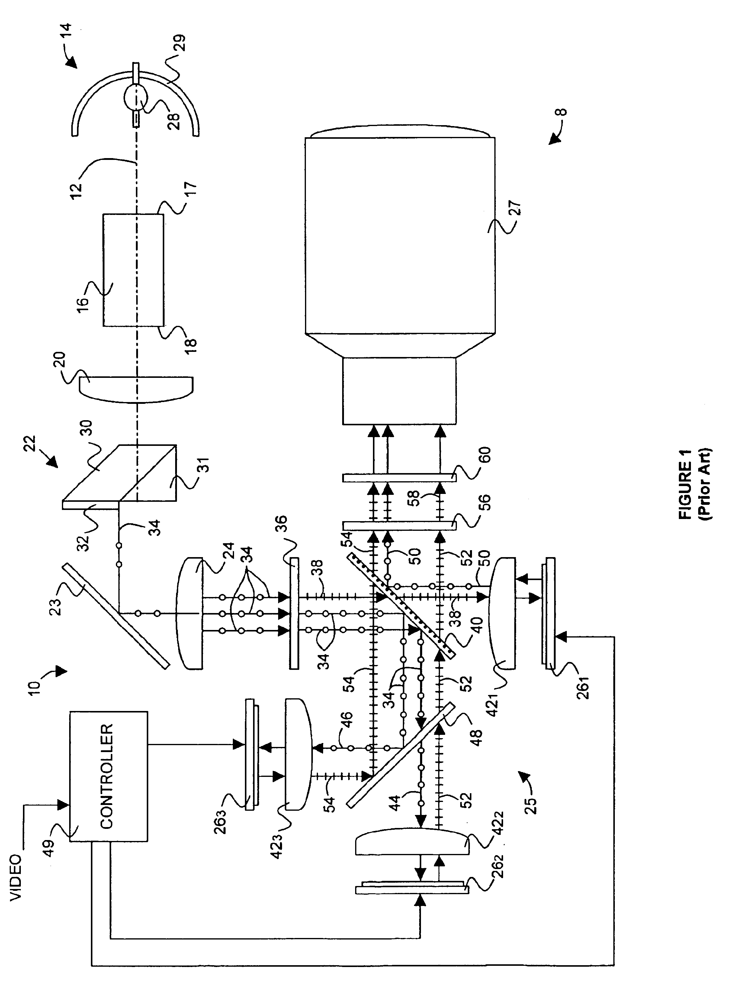
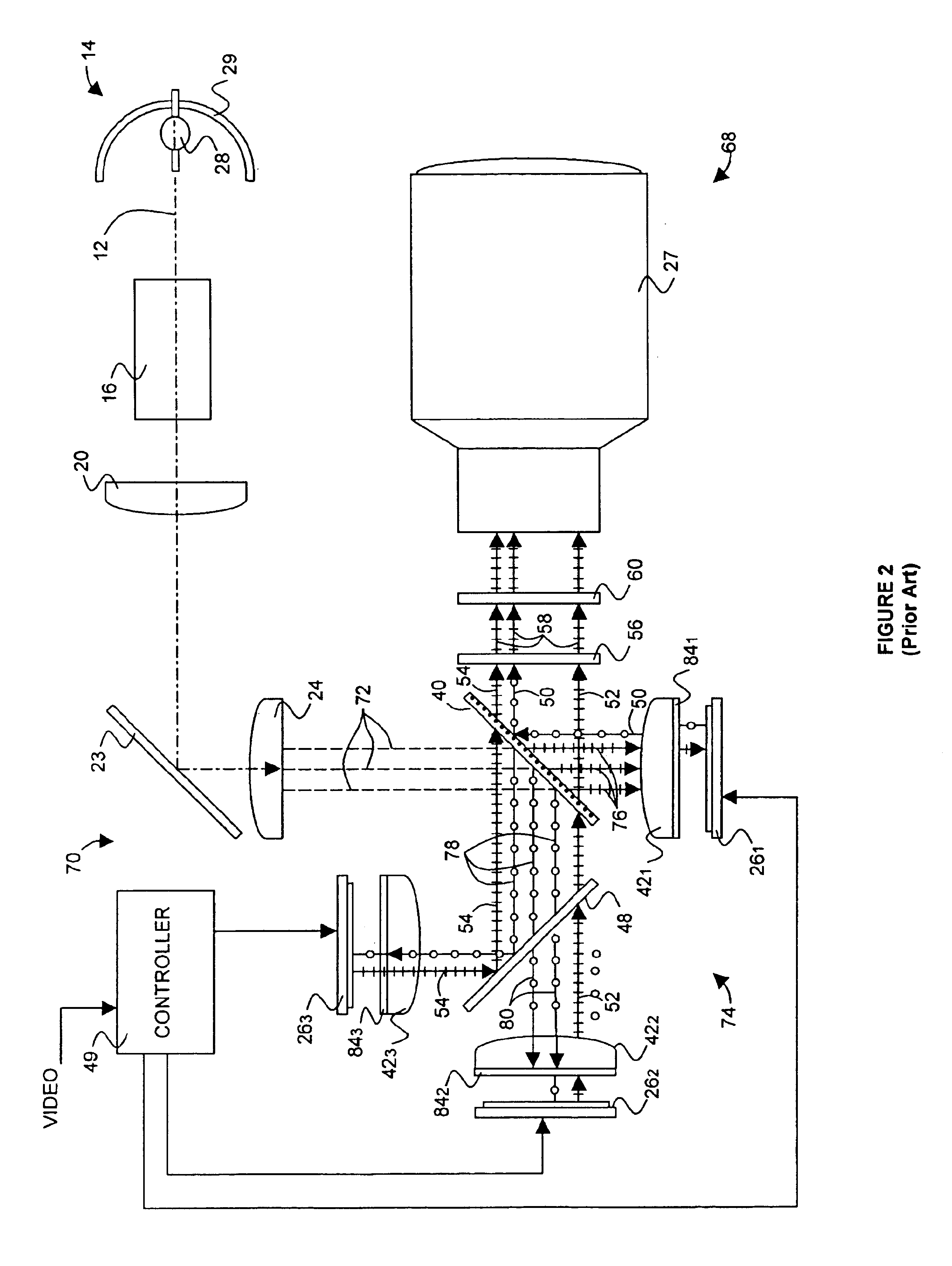
FIG. 3 shows a basic single-path multimedia projector 100 of this invention. Single-path projector 100 is a further simplification of three-path projector 68 of FIG. 2. However, projector 100 further includes a color modulator, such as a liquid crystal-based color switcher, or preferably a color wheel 102, a wavelength-selective light sensor 104, and replaces controller 49 with an FSC controller 106. Projector 100 does not require LCDs 262 and 263, field lenses 422 and 423, trim filters 84, dichroic filter plate 48, nor spectrically selective output wave plate 56. Clean-up polarizer 60 is optional as described below.
Polychromatic light rays emitted by arc lamp 28 are converged by elliptical reflector 29 to propagate along optical axis 12 through color filter segments of color wheel 102 and optical integrator 16. Color wheel 102 preferably includes R, G, B, and light-purplish filter segments. Because the light from arc lamp 28 is typically greenish (deficient in red), the light-purpl...
second embodiment
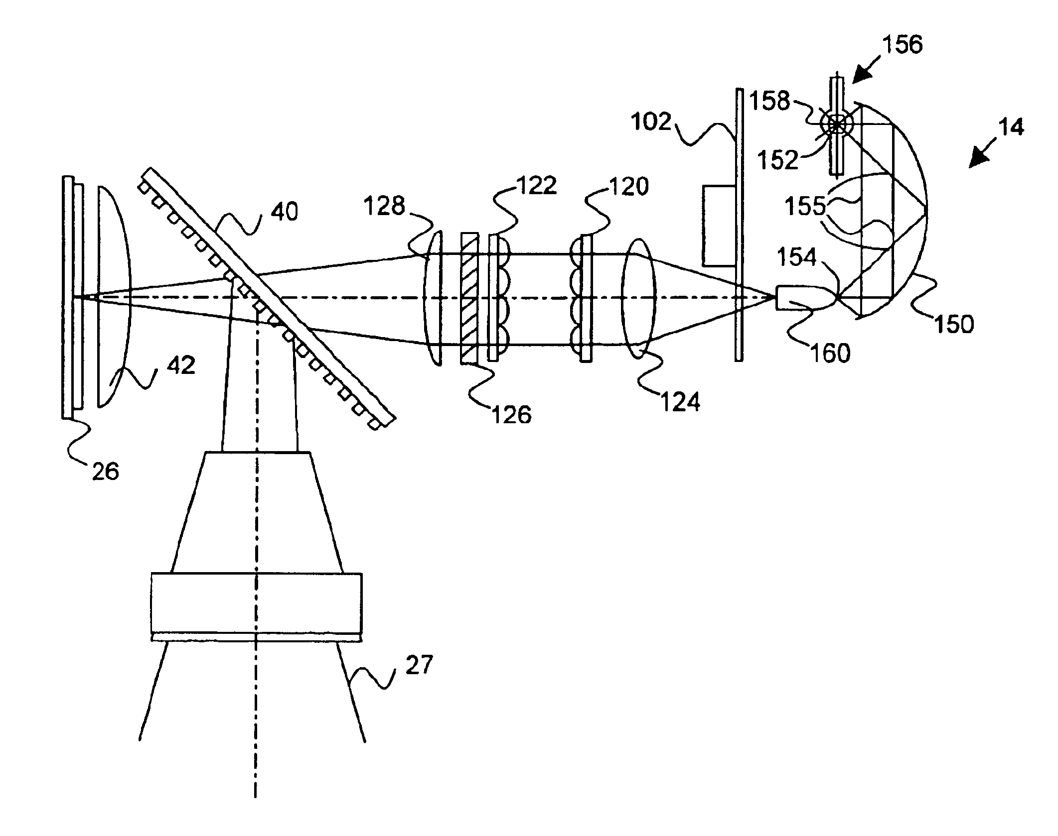
FIG. 4 shows the invention in which the light-transmission efficiency of single-path projector 100 is increased by replacing optical integrator 16 with first and second flyseye lenses 120 and 122, which function best with a collimated light source. Accordingly, a collimating lens 124 is placed between color wheel 102 and first flyseye lens 120. A PCA 126 and a condenser lens 128 are placed in the light path following first and second flyseye lenses 120 and 122 to focus the uniform polarized light through transflective polarizing beam splitter 40 and field lens 42 onto LCD 26. This embodiment is simplified by eliminating optional fold mirror 23 of FIGS. 1, 2, and 3. Otherwise the image projection functionality of this embodiment is substantially the same as the FIG. 3 embodiments.
third embodiment
FIG. 5 shows this invention in which single-path projector 100 is simplified by replacing color wheel 102 with a liquid crystal-based color-switching device 130 that provides the required sequential light path switching through a predetermined set of colors. As in the FIG. 4 embodiment, this embodiment includes first and second flyseye lens arrays 120 and 122, PCA 126, and condenser lens 128, but does not include optional fold mirror 23. Color-switching device 130 is preferably placed between condenser lens 128 and transflective polarizing beam splitter 40. This embodiment is further simplified by replacing collimating lens 124 with a collimating reflector 132 in light source 14. Space is saved by placing light source 14 close to first flyseye lens 120 and providing an intervening UV / IR filter 134 as a heat shield. Otherwise the image projection functionality of this embodiment is substantially the same as the FIG. 3 embodiments.
PUM
 Abstract
Description
Claims
Application Information