Versatile microscope system with modulating optical system

a microscope system and optical system technology, applied in the field of microscope systems, can solve the problems of inability to adjust, complicated handling, and difficult to set the optimum value in the variable portion, and achieve the effect of optimum image quality simply and accurately

Inactive Publication Date: 2005-01-04
OLYMPUS CORP
View PDF5 Cites 35 Cited by
  • Summary
  • Abstract
  • Description
  • Claims
  • Application Information

AI Technical Summary

Benefits of technology

It is an object of the invention to present a microscope as a versatile microscopic apparatus capable of obtaining images of optimum image quality simply and accurately, in various objects in a wide range, and an image analysis method using the same.
According to the twelfth and twenty-fourth aspects of the invention, the configuration of the parameter determining device (means) is defined more specifically. According to this configuration, various parameters for obtaining the adequate image can be set objectively, and easily and accurately.

Problems solved by technology

However, usually the pupil modulating element 507 is realized by a fixed film by coating, and cannot be adjusted.
Actually, however, as the versatility is enhanced, it is more difficult to set the optimum value in the variable portion.
In this case, the objects may be reduced to a certain extent, but if desired to handle various objects accurately, more parameter tables are needed, and handling is more complicated.
To the contrary, if the number of tables is decreased to avoid such complicated handling, it is hard to achieve optimum handling in more objects.
Thus, in the microscopic apparatus of the prior art, it is hard to set various parameters by the variable pupil modulating element introduced for achieving the versatility optimally in various objects in a wide range, which is one of the serious problems for achieving the practical use.

Method used


Image

  • Versatile microscope system with modulating optical system
  • Versatile microscope system with modulating optical system
  • Versatile microscope system with modulating optical system

Examples


first embodiment

(First Embodiment)

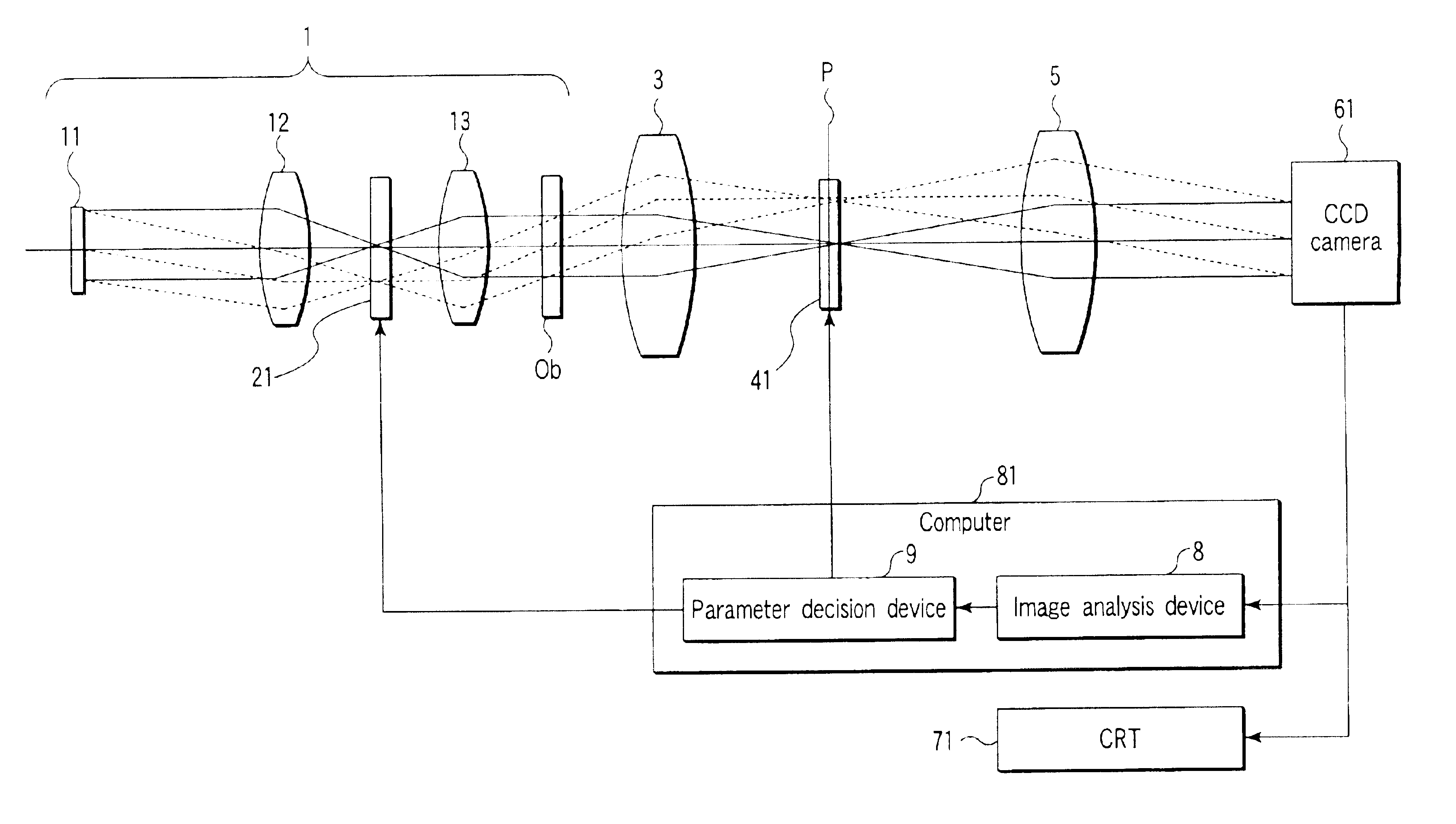
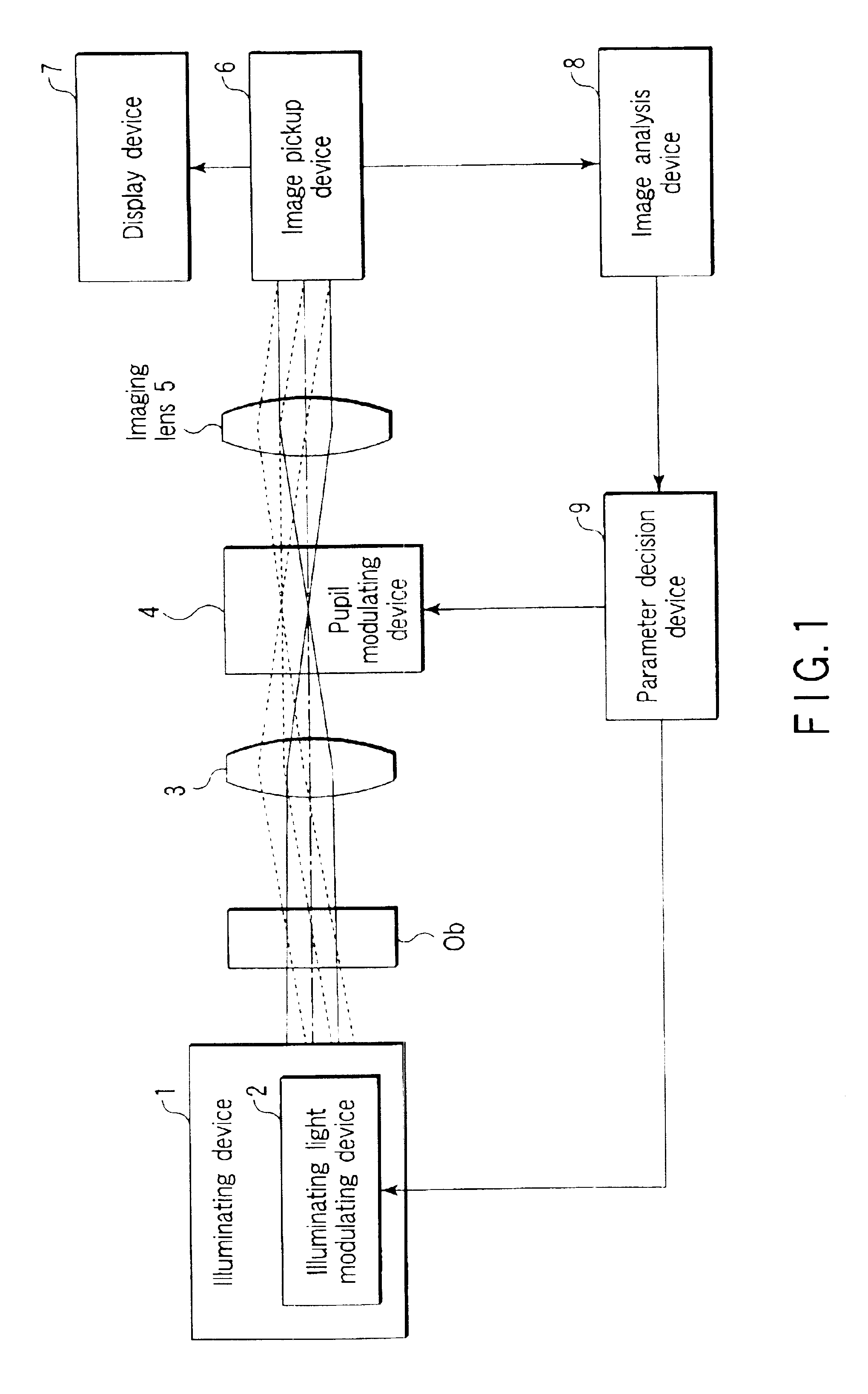
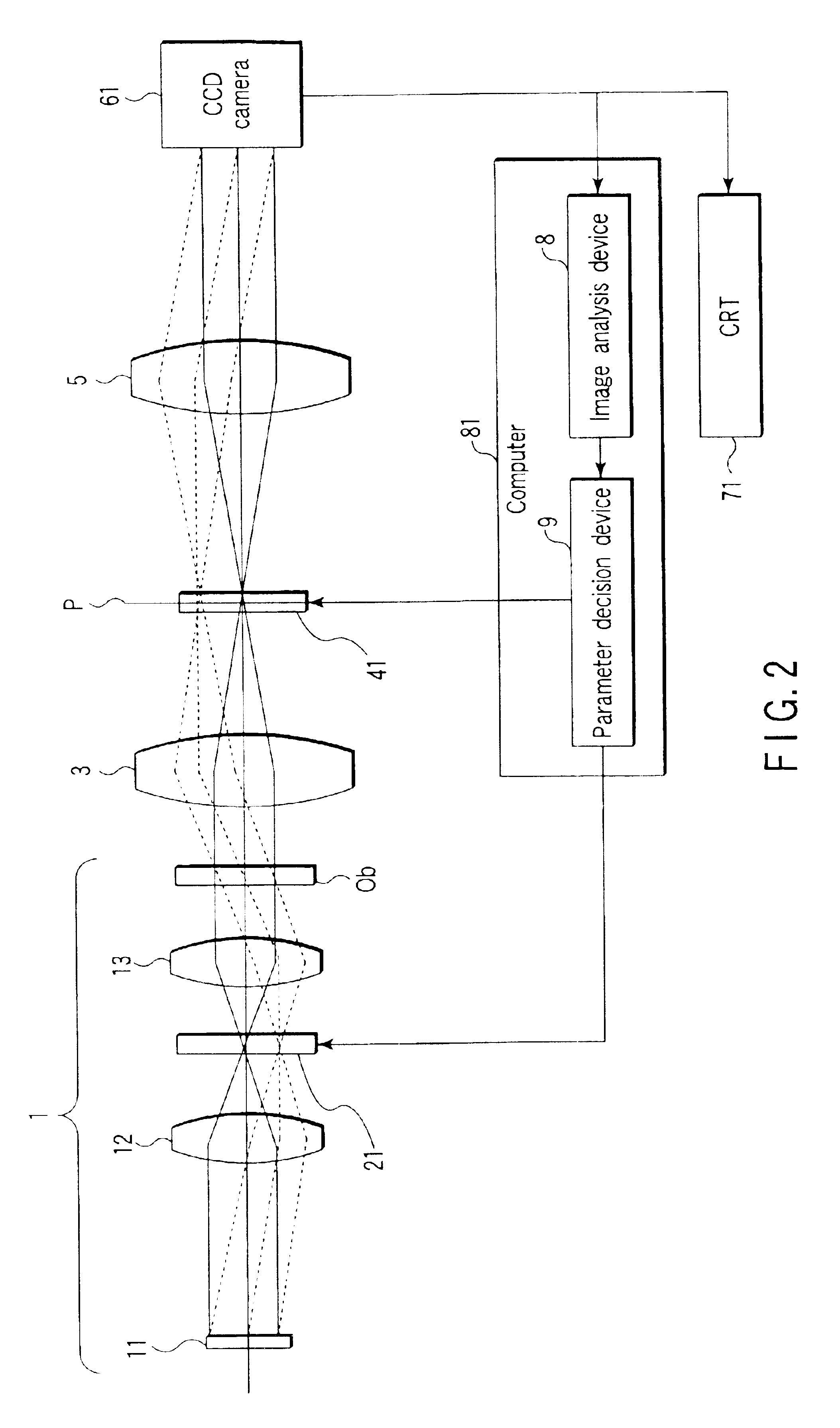
FIG. 1 is a block diagram showing a configuration of a microscopic apparatus according to a first embodiment of the invention.

That is, as shown in FIG. 1, the microscopic apparatus in the first embodiment of the invention comprises: an illuminating device 1 for generating a luminous flux for reading out information of the object and emitting the luminous flux to the object; an illuminating light modulating device 2 for modulating at least one of phase, intensity, and direction of polarization of the luminous flux; an objective lens 3 and an imaging lens 5 for forming an image of the object by the luminous flux reading out the information of the object; an image pickup device 6 for picking up the image of the object; a pupil modulating device 4 disposed near the pupil plane of the objective lens 3, for modulating at least one of phase, intensity, and direction of polymerization; a display device 7 for displaying the observed image acquired in the image pickup device...

fourth example

FIG. 10 is a block diagram showing a configuration of a versatile microscopic apparatus according to a fourth example of the first embodiment of the invention.

That is, the versatile microscopic apparatus in the fourth example of the first embodiment of the invention is, as shown in FIG. 10, similar to the first example of the first embodiment except for the following points: the pupil plane of the objective lens 3 is placed within the lens barrel of the objective lens 3; and the analysis items of the image analysis device 8 and the portion of the parameter decision device 9 are changed.

This example shows a case of observation method similar to Hoffman modulation contrast observation using an oblique illumination.

In this case, a slit pattern as shown in FIG. 11A is displayed in the liquid crystal spatial light modulating element 21 for illumination modulation (in the diagram, the white portion corresponds to the portion of transmissivity of 1, and the solid black portion corresponds ...

second embodiment

FIG. 13 is a block diagram showing a configuration of a versatile microscopic apparatus according to a second embodiment of the invention.

That is, the versatile microscopic apparatus in the second embodiment of the invention is, as shown in FIG. 13, characterized by disposing a pupil transmission optical system 10 between the objective lens 3 and the imaging lens 5 in the first embodiment, thereby forming newly an image plane P2 conjugate with the pupil P1 of the objective lens 3, in which the pupil provided inside of the lens barrel of the objective lens in most cases of the microscope is disposed on the outside so as to eliminate mechanical restrictions about installation of the pupil modulating device 4.

Other configuration and functional effect of the embodiment are same as in the first embodiment.

Incidentally, by inserting a plurality of pupil transmission optical systems 10, image planes conjugate with the pupil P1 of the objective lens can be newly formed by the same number.

FI...


PUM

PropertyMeasurementUnit
luminous fluxaaaaaaaaaa
wavelengthaaaaaaaaaa
phaseaaaaaaaaaa

Abstract

An illuminating light modulating device modulates at least one of wavelength, phase, intensity, polarization, and coherency of the light emitted to an object by an illuminating device. A pupil modulating device is disposed near a pupil plane of an objective lens, and modulates at least one of phase, intensity and direction of polarization of the luminous flux including the information of the object. An image pickup device is disposed on a plane on which the image of the object is formed by the objective lens and an imaging lens, and picks up the image of the object. An image analysis device analyzes the image of the object picked up by the image pickup device. A parameter decision device adjusts the modulation amounts of the illuminating light modulating device and the pupil modulating device by using the image information of the object analyzed by the image analysis device.

Description

CROSS-REFERENCE TO RELATED APPLICATIONSThis application is based upon and claims the benefit of priority from the prior Japanese Patent Applications No. 2001-242635, filed Aug. 9, 2001; and No. 2002-192665 filed Jul. 1, 2002, the entire contents of both of which are incorporated herein by reference.BACKGROUND OF THE INVENTION1. Field of the InventionThe present invention relates to a microscope system, and more particularly to a microscope having a modulating optical system for modulating a luminous flux from an object as a versatile microscopic apparatus, and an image analysis method using the same.2. Description of the Related ArtGenerally, the microscope requires various adjustments in order to obtain favorable images, such as adjustment of aperture stop and field stop, modulation on a pupil plane, and other adjustments depending on the object of observation and NA of objective lens.A typical example is a phase contrast microscope.The phase contrast microscope is briefly explaine...

Claims


Application Information

Patent Timeline
Patent Type & Authority Patents(United States)
IPC IPC(8): G02B21/14G02B21/06G02B21/00G02B21/36G02F1/01G02F1/13
CPCG02B21/14G02B21/086
Inventor FUKUSHIMA, IKUTOSHIHASHIMOTO, TAKESHINAMIKI, MITSURUMINAKATA, HIROYUKIYAMAMOTO, KIMIAKI
Owner OLYMPUS CORP
Why Eureka
Try Eureka