Two-dimensional, anti-scatter grid and collimator designs, and its motion, fabrication and assembly

Inactive Publication Date: 2005-01-04
CREATV MICROTECH
View PDF21 Cites 15 Cited by
  • Summary
  • Abstract
  • Description
  • Claims
  • Application Information

AI Technical Summary

Benefits of technology

These and other objects are further substantially achieved by providing a method for minimizing scattering of electromagnetic energy in an electromagnetic imaging device which is adapted to obtain an image of an object on an imager. The method includes placing a grid between an electromagnetic energy emitting source of the electromagnetic imaging device and the imager. The grid comprises at least one metal layer including top and bottom surfaces and a plurality of solid integrated, int

Problems solved by technology

It is undesirable to have the grid shadow show artificial patterns.
This grid pattern and the associat

Method used


Image

  • Two-dimensional, anti-scatter grid and collimator designs, and its motion, fabrication and assembly
  • Two-dimensional, anti-scatter grid and collimator designs, and its motion, fabrication and assembly
  • Two-dimensional, anti-scatter grid and collimator designs, and its motion, fabrication and assembly

Examples


Embodiment Construction

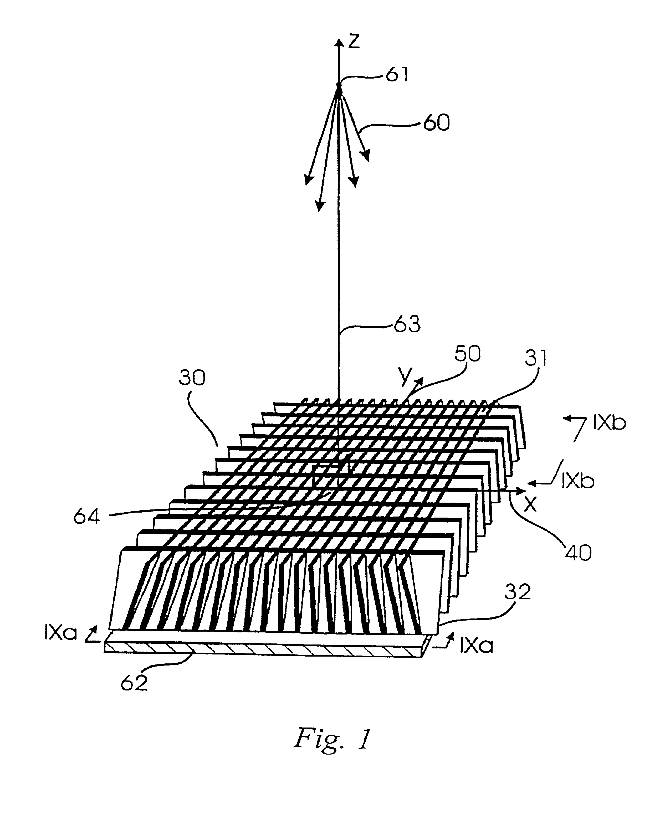
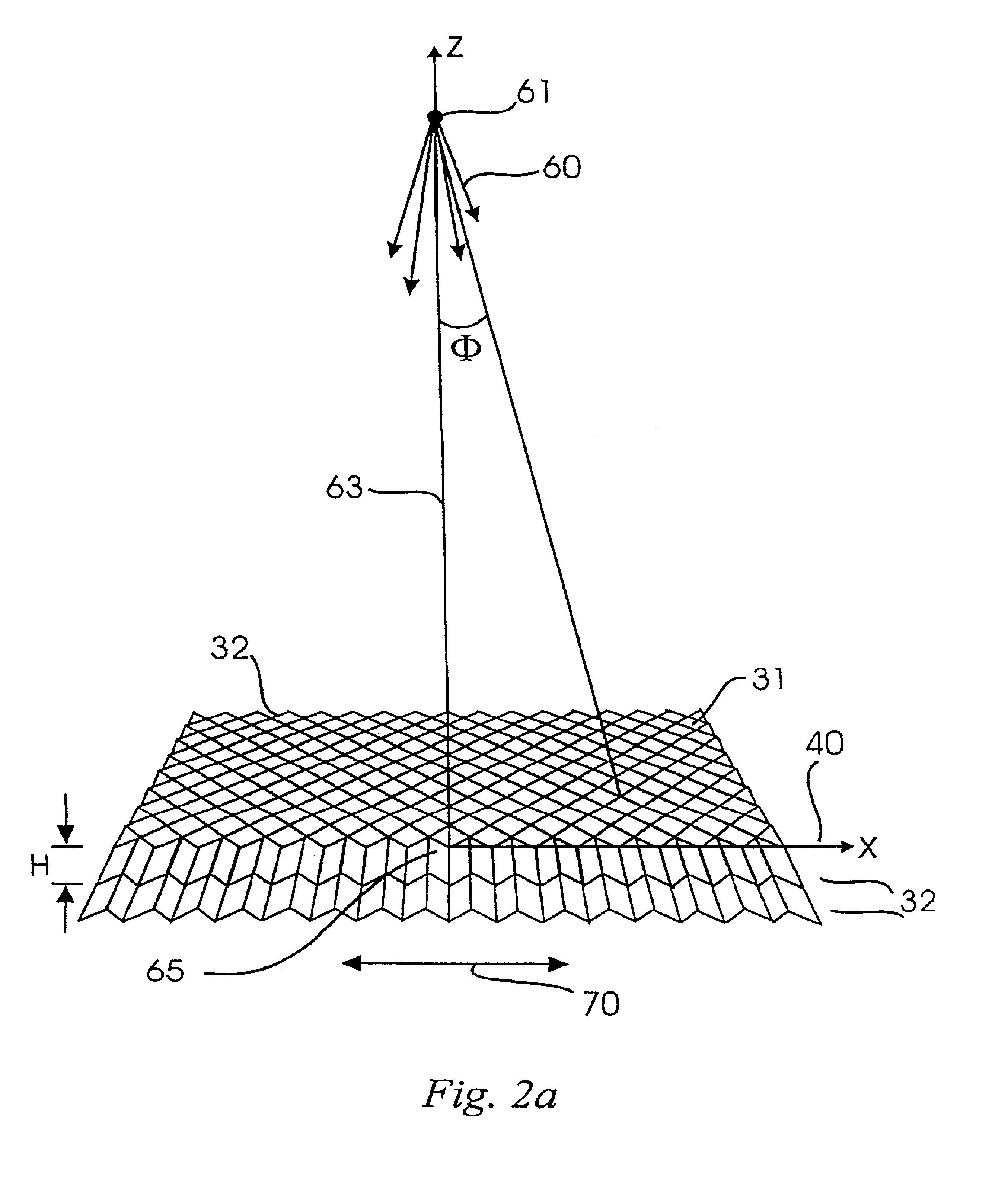
The present invention provides a method and apparatus for making large area, two-dimensional, high aspect ratio, focused or unfocused x-ray anti-scatter grids, anti-scatter grid / scintillators, x-ray filters, and the like, as well as similar methods and apparatus for ultraviolet and gamma-ray applications. Referring now to the drawings, FIG. 1 shows a schematic of a section of a two-dimensional, focused anti-scatter grid 30 produced by a method of grid manufacture according to an embodiment of the present invention, as described in more detail in U.S. Pat. No. 5,949,850 referenced above.

The object to be imaged (not shown) is positioned between the x-ray source and the x-ray grid 30. The grid openings 31 which are defined by walls 32 are square in this example. However, the grid openings can be any practical shape as would be appreciated by one skilled in the methods of grid construction. The walls 32 are uniformly thick or substantially uniformly thick around each opening in this fig...


PUM


Abstract

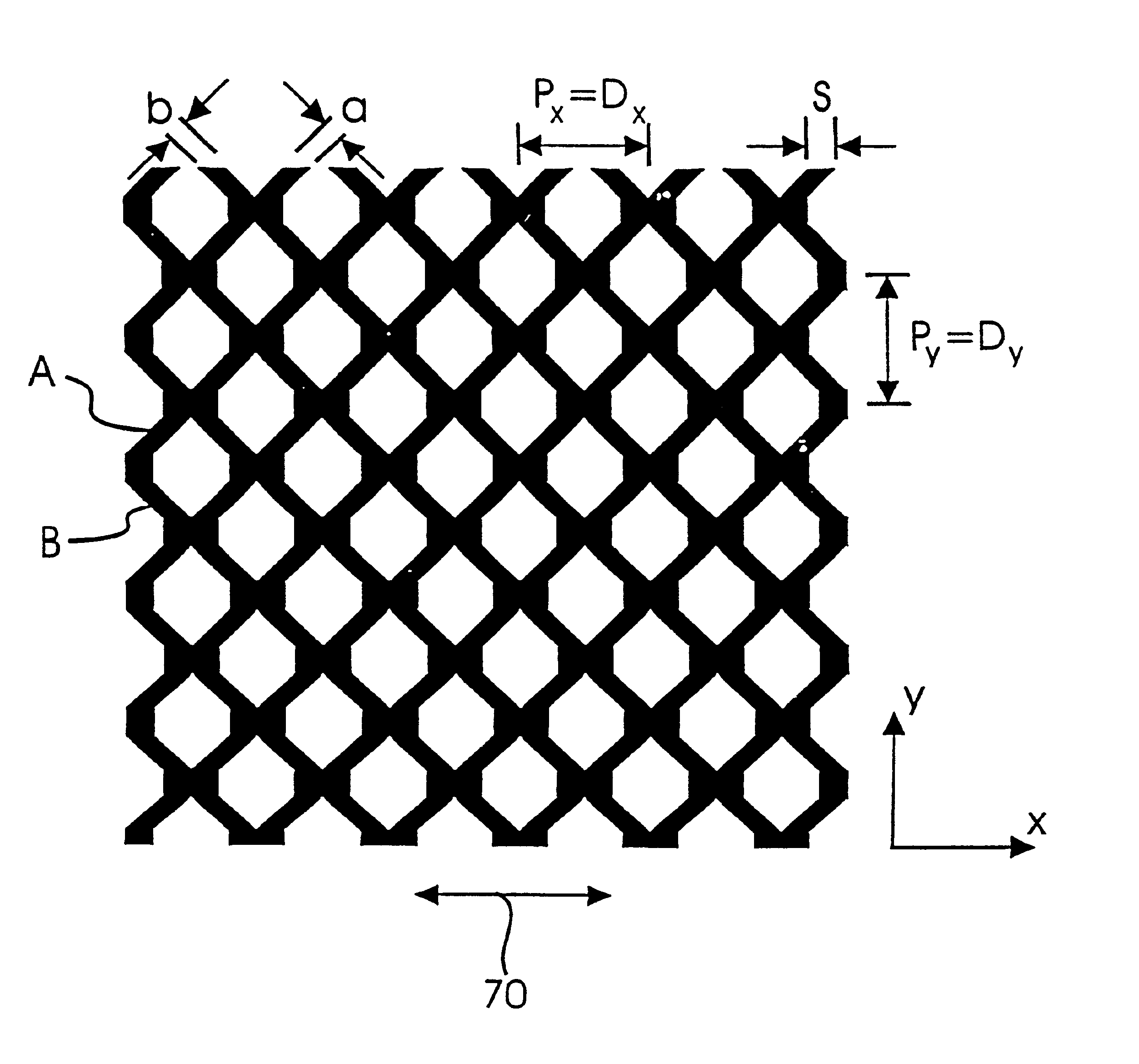
A grid, for use with electromagnetic energy emitting devices, includes at least metal layer, which is formed, for example, by electroplating. The metal layer includes top and bottom surfaces, and a plurality of solid integrated walls. Each of the solid integrated walls extends from the top to bottom surface and having a plurality of side surfaces. The side surfaces of the solid integrated walls are arranged to define a plurality of openings extending entirely through the layer. At least some of the walls also can include projections extending into the respective openings formed by the walls. The projections can be of various shapes and sizes, and are arranged so that a total amount of wall material intersected by a line propagating in a direction along an edge of the grid is substantially the same as another total amount of wall material intersected by another line propagating in another direction substantially parallel to the edge of the grid at any distance from the edge.

Description

BACKGROUND OF THE INVENTION1. Field of the InventionThe present invention relates to a method and apparatus for making focused and unfocused grids and collimators which are movable to avoid grid shadows on an imager, and which are adaptable for use in a wide range of electromagnetic radiation applications, such as x-ray and gamma-ray imaging devices and the like. More particularly, the present invention relates to a method and apparatus for making focused and unfocused grids, such as air core grids, that can be constructed with a very high aspect ratio, which is defined as the ratio between the height of each absorbing grid wall and the thickness of the absorbing grid wall, and that are capable of permitting large primary radiation transmission therethrough.2. Description of the Related ArtAnti-scatter grids and collimators can be used to eliminate the scattering of radiation to unintended and undesirable directions. Radiation with wavelengths shorter than or equal to soft x-rays ca...

Claims


Application Information

Patent Timeline
IPC IPC(8): G21K1/02
CPCG21K1/025
Inventor TANG, CHA-MEI
Owner CREATV MICROTECH
Why Eureka
Try Eureka