Method of manufacture of damascene reticle
a damascene and reticle technology, applied in the field of damascene reticle manufacturing, can solve the problems of etching cog reticles, affecting the production efficiency of damascene, and consuming the photoresist mask very quickly, so as to reduce the scattering of light, improve the imaging performance, and eliminate the growth of defects
- Summary
- Abstract
- Description
- Claims
- Application Information
AI Technical Summary
Benefits of technology
Problems solved by technology
Method used
Image
Examples
first embodiment
of a Damascene Mask Plate Formed in a Transparent Reticle Mask Plate
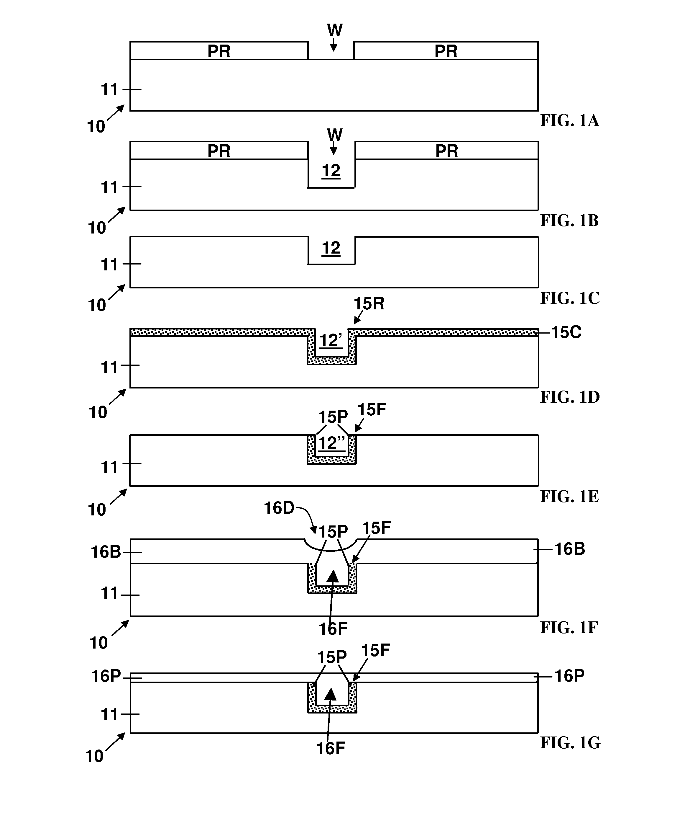
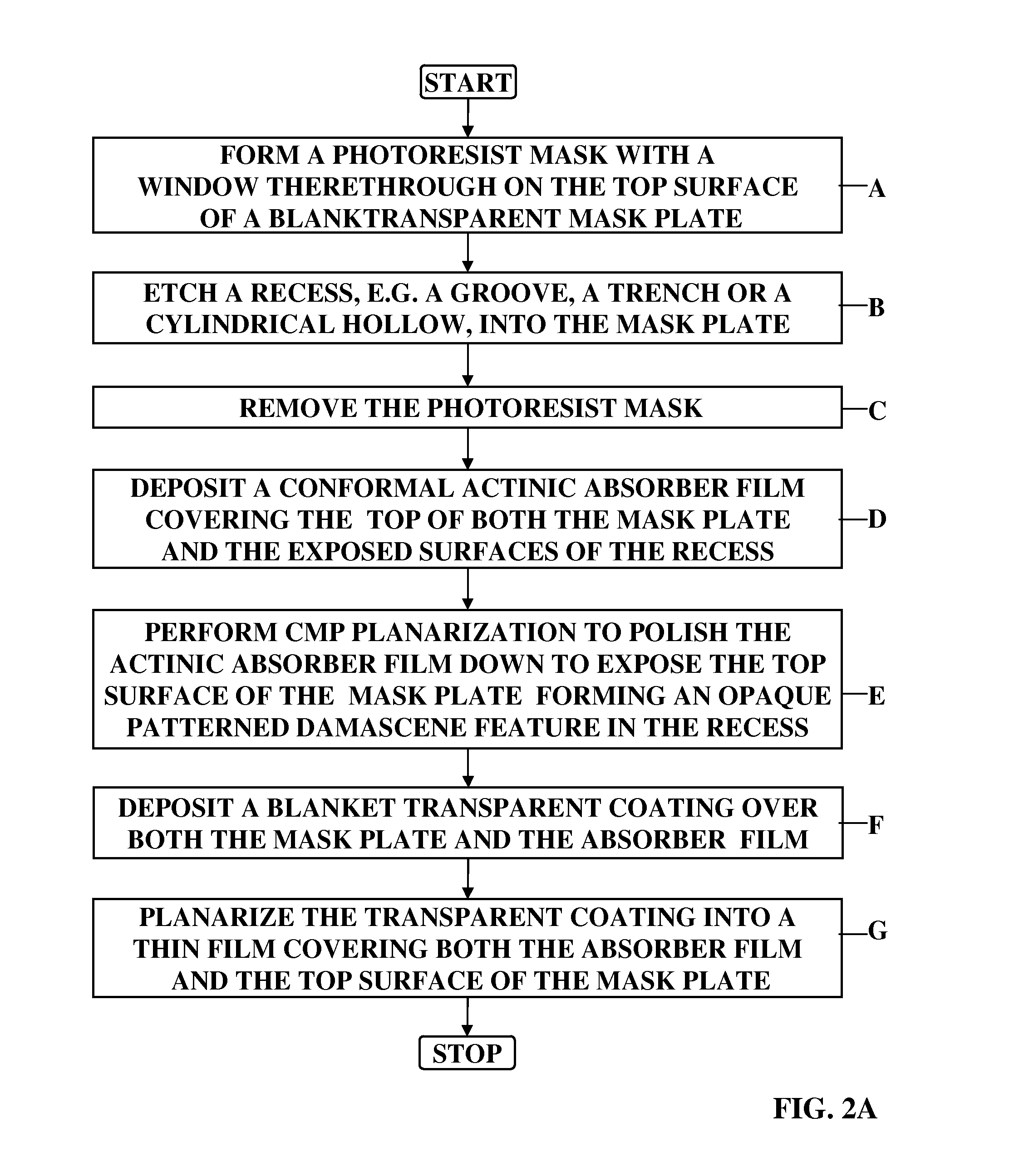
[0065]Heretofore, mask plate reticles have been formed by patterning opaque material on the top surface of a transparent substrate. In accordance with this invention a damascene mask plate is formed by first forming a pattern of recesses in a blank, transparent, reticle mask plate. Then the recesses are filled with opaque and / or partially transmissive materials depending upon which type of damascene mask plate is being formed in accordance with this invention. Several embodiments thereof are described below with reference to the appended drawings. The substrate can be selected to be transparent for an exposure radiation of an appropriate wavelength to be used with such mask plate reticles. FIGS. 1A-1F are schematic, elevational sections of a reticle 10 formed from a blank transparent reticle mask plate 11 (hereinafter mask plate 11). The process of manufacture provides a patterned damascene reticle 10 shown in FIG. ...
second embodiment
icle
[0076]FIGS. 3A-3F are schematic elevational views of a damascene PSM reticle 30 during the process of manufacture of the reticle in accordance with another aspect of the method of this invention, as shown by the flow chart of FIG. 4. FIGS. 3A-3F illustrate process flow for patterning the reticle 30. As shown in FIG. 3F, the resulting reticle 30 has PSM features 36F′ which are composed of deposited conformal film elements 33P / 35P filling a feature recess 32 in a mask plate 31. The reticle 30 is adapted to be used to expose patterns on a workpiece (not shown.) FIG. 3F shows a patterned reticle 30 which is to be employed as a PSM mask after the manufacture thereof in accordance with this invention for exposing patterns formed thereon.
[0077]FIG. 3A shows the reticle 30 in an initial, stage of processing in accordance with step A in FIG. 4. A transparent reticle mask plate 31 (hereinafter mask plate 31) is shown with a top surface on which a photoresist mask PR is formed. As with FIG...
third embodiment
ticle In-Situ Lens Formation on the Reticle
[0085]In a modification of the embodiment of FIG. 3F, aside from the detail that the shape and index of refraction of the outer, partially-transmissive, remainder element 33P is tuned so that parallel focused light beams come out of the top side of the reticle 30 as illumination is to be projected from below for all images. Improvements can employ multiple different layers with varying refraction indexes to improve the focus effect.
PUM
 Abstract
Description
Claims
Application Information
 - R&D
- Intellectual Property
- Life Sciences
- Materials
- Tech Scout
- Unparalleled Data Quality
- Higher Quality Content
- 60% Fewer Hallucinations
Browse by: Latest US Patents, China's latest patents, Technical Efficacy Thesaurus, Application Domain, Technology Topic, Popular Technical Reports.
© 2025 PatSnap. All rights reserved.Legal|Privacy policy|Modern Slavery Act Transparency Statement|Sitemap|About US| Contact US: help@patsnap.com


