
Battery and method for manufacturing the same

a battery and manufacturing method technology, applied in the field of batteries, can solve the problems of affecting battery performance, affecting battery performance, and causing a tendency to produce forth and other foreign matter, and achieve the effect of stable manufacturing

Active Publication Date: 2013-11-12
TOYOTA JIDOSHA KK
View PDF9 Cites 2 Cited by
  • Summary
  • Abstract
  • Description
  • Claims
  • Application Information

AI Technical Summary

Benefits of technology

[0007]The present invention was conceived in light of this situation, and it is a main object thereof to provide a battery comprising a collecting structure with which the scattering of welding spatter and other such foreign matter (and particularly its working its way into the interior of the electrode body) during welding can be minimized. Also provided is a manufacturing method with which a battery having such performance can be stably manufactured.

Problems solved by technology

With a battery configured as above, however, a problem is that welding spatter (such as metal particles that melt during welding and scatter in the form of sparks) and so forth and other such foreign matter tends to be produced in the welding of the current collecting plate to the bottom face of the battery case.
When welding spatter or the like occurs, not only does it scatter around the periphery of the weld and adversely affect the welding quality, but it can work its way into the battery case through the gap between the current collecting plate and the battery case, where it can become a source of diminished battery performance, such as internal shorting of the electrode body.
This type of welding spatter is difficult to detect when it occurs, and consequently it is currently impossible to prevent the scattering of this spatter merely by adjusting the welding conditions.

Method used


Image

  • Battery and method for manufacturing the same
  • Battery and method for manufacturing the same
  • Battery and method for manufacturing the same

Examples


Embodiment Construction

[0030]The best mode for carrying out the invention will now be described through reference to the drawings. In the following drawings, those components that have the same action are numbered the same. The structure of the battery of the present invention will now be described in detail by using a cylindrical lithium ion secondary battery as an example, but the present invention is not intended to be limited to what is stated in the embodiments. Also, the dimensional relationships in the drawings (length, width, thickness, etc.) do not reflect the actual dimensional relationships.

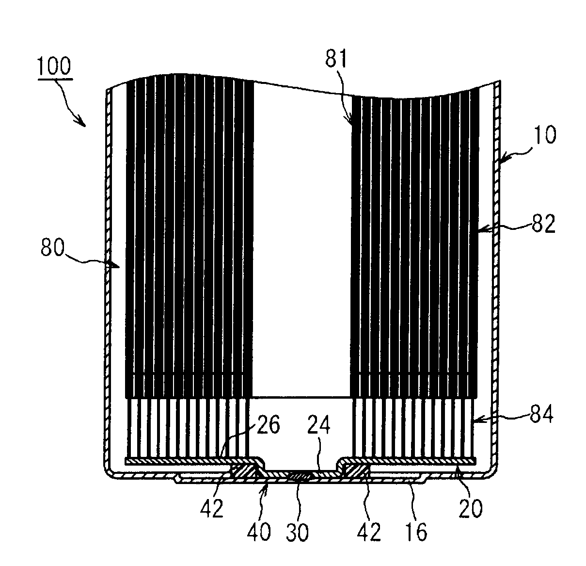
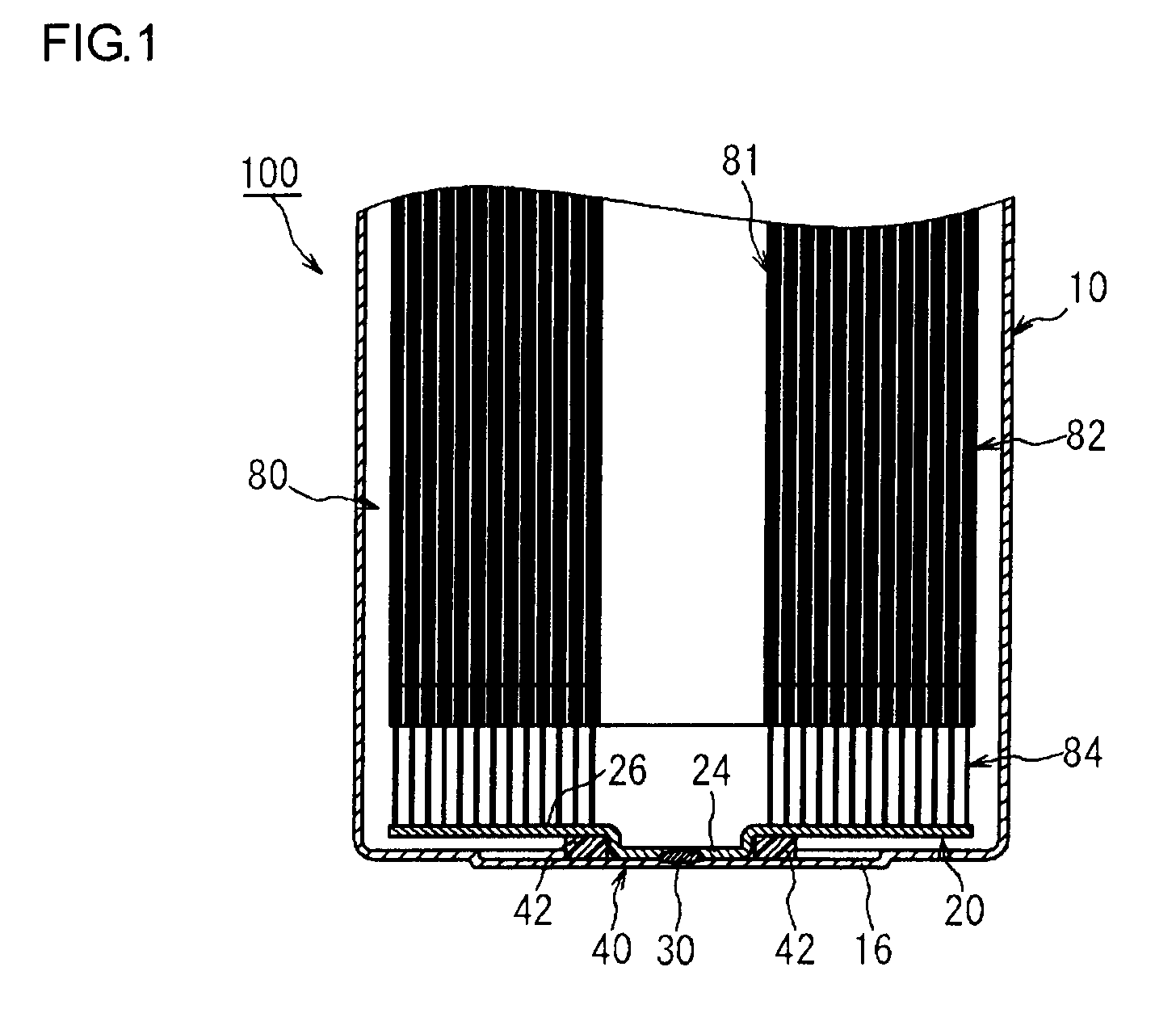
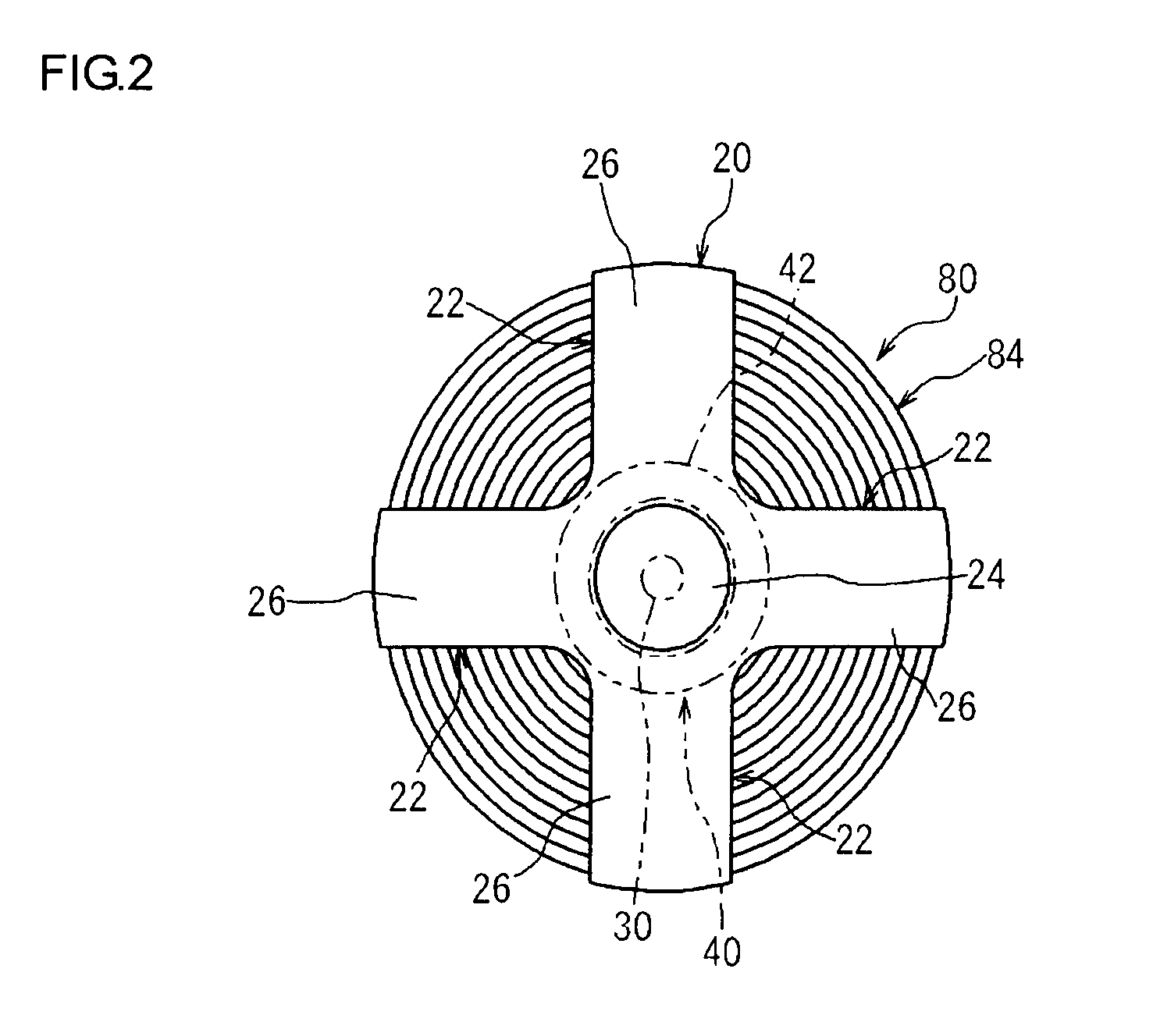
[0031]A lithium ion secondary battery 100 of this embodiment will be described through reference to FIG. 1. FIG. 1 is a cross section that schematically illustrates the main parts of the battery 100. The lithium ion secondary battery 100 pertaining to this embodiment is what is called a sealed battery, in which the internal space of the battery case is spatially isolated from the outside (hereinafter also re...


PUM

PropertyMeasurementUnit
elasticaaaaaaaaaa
shapeaaaaaaaaaa
weightaaaaaaaaaa

Abstract

A battery (100) provided by the present invention includes an electrode body (80) having a positive electrode and a negative electrode (84), a bottomed battery case (10) for holding the electrode body (80), and a current collecting plate (20) that connects the battery case (10) with either the positive electrode or the negative electrode of the electrode body. A part of the current collecting plate (20) and a bottom part (16) of the battery case (10) are fixed to each other by welding, and a sealed structure (40) that surrounds a weld (30) composed of a portion that has been welded is formed at the periphery of the weld (30).

Description

TECHNICAL FIELD[0001]This invention relates to a battery, and more particularly relates to a battery in which a current collecting plate and a battery case are joined by welding, and to a method for manufacturing this battery.[0002]This international application claims priority right on the basis of Japanese Patent Application No. 2008-104352 submitted on Apr. 14, 2008, and the entire content of that application is incorporated by reference into this specification.BACKGROUND ART[0003]Recent years have seen rising demand for lithium ion batteries, nickel-hydrogen batteries, and other such secondary batteries as power sources installed in vehicles, as well as power supplies for personal computers and portable terminals. In particular, it is anticipated that lithium ion batteries can be used to advantage as high-output power supplies installed in vehicles because of their light weight and high energy density.[0004]Among the lithium ion batteries of this type, a cylindrical battery, for...

Claims


Application Information

Patent Timeline
Patent Type & Authority Patents(United States)
IPC IPC(8): H01M2/02H01M4/82H01R43/02H01M50/107H01M50/538
CPCH01M2/0202H01M2/263H01M2/34H01M2/022Y02E60/10H01M50/107H01M50/538H01M50/572H01M50/531Y10T29/4911Y10T29/49213
Inventor KIYAMA, AKIRA
Owner TOYOTA JIDOSHA KK
Learn More