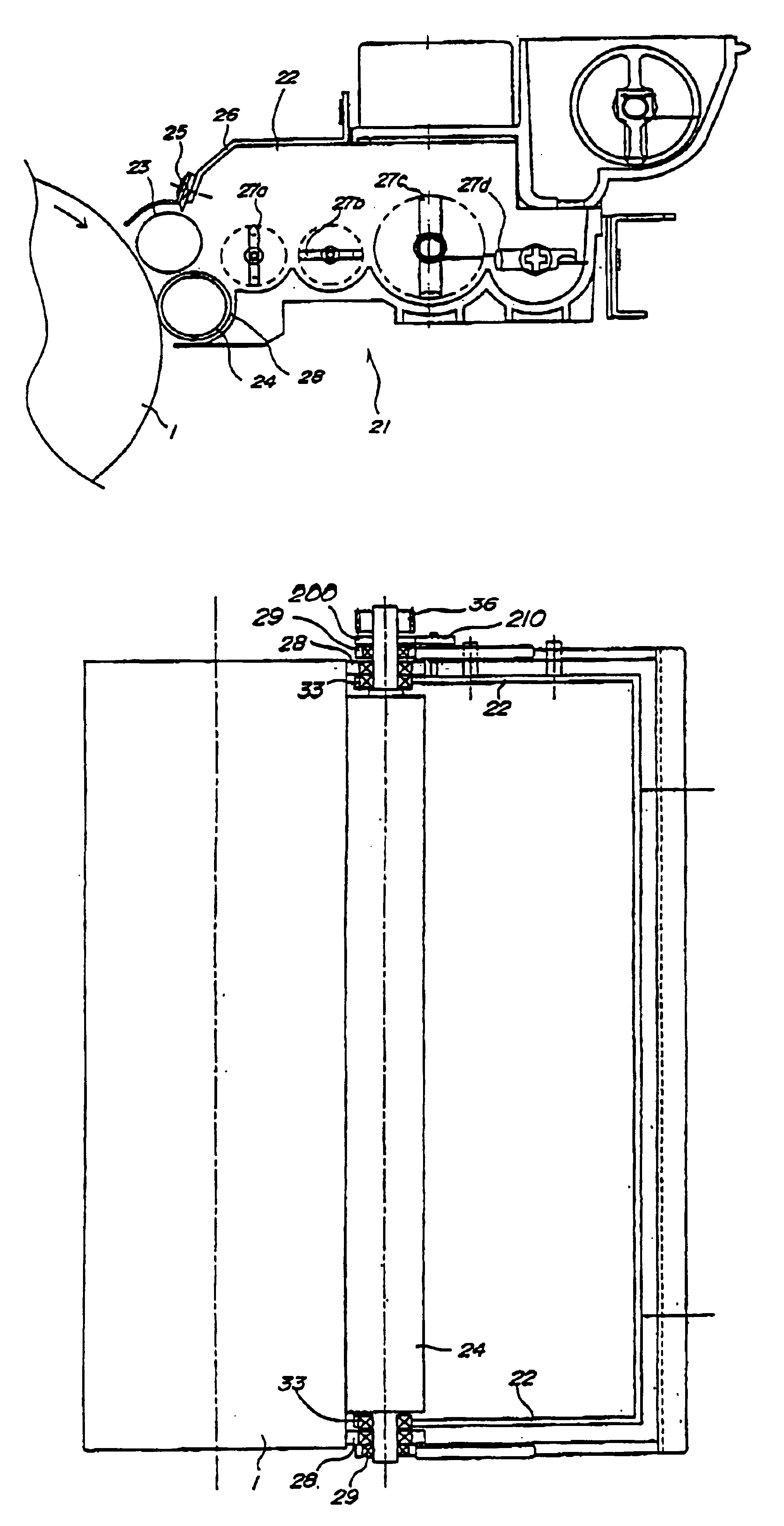
Developing apparatus

a technology of developing apparatus and developing member, which is applied in the direction of electrographic process apparatus, instruments, optics, etc., can solve the problems of affecting affecting the stability of the developing member, and the inability to guarantee the main gap, etc., to achieve the effect of stable development property and not increasing the rotational load of the developing member

Inactive Publication Date: 2005-01-04
CANON KK
View PDF8 Cites 2 Cited by
  • Summary
  • Abstract
  • Description
  • Claims
  • Application Information

AI Technical Summary

Benefits of technology

It is an object of the invention to provide a developing apparatus providing a stable developing property not increasing rotational load of a developing member.
It is another object of the invention to provide a developing apparatus not increasing rotational load of a developing member as preventing the developing property from lowering.

Problems solved by technology

Conversely, if the pressing force is high, the developing container or the developing sleeve 111 may be subject to stressing, and it is impossible to guarantee main gaps.
Moreover, this may disturb rotation of the photosensitive body and the developing sleeve 111, and also may grind the striking rollers 121a, 121b during the use.
That is, there raises a problem that the developing sleeve rotation load torque increases due to toner leakage from the widen gap or due to toner adherence from the reduced gap.

Method used


Image

  • Developing apparatus
  • Developing apparatus
  • Developing apparatus

Examples


Embodiment Construction

Referring to the drawings, a developing apparatus and an image forming apparatus having this developing apparatus as embodiments according to the invention are described. FIG. 5 is a schematic cross section showing an outlined structure of an image forming apparatus.

As shown in FIG. 5, an image forming apparatus according to this embodiment reads images on an original document at an image reading section 8 and forms electrostatic latent images on a photosensitive drum 1 as a latent image carrier by rendering exposure from an image writing section 9 on a surface of the photosensitive drum 1 according to commands from a controller, not shown, based on the read image data.

It is to be noted that where the surface of the photosensitive drum 1 is charged uniformly at a prescribed potential by a charger 2 before the exposure, the electrostatic latent image is formed on the photosensitive drum 1 by radiating laser beam or the like from the image writing section 9 on the photosensitive drum ...


PUM


Abstract

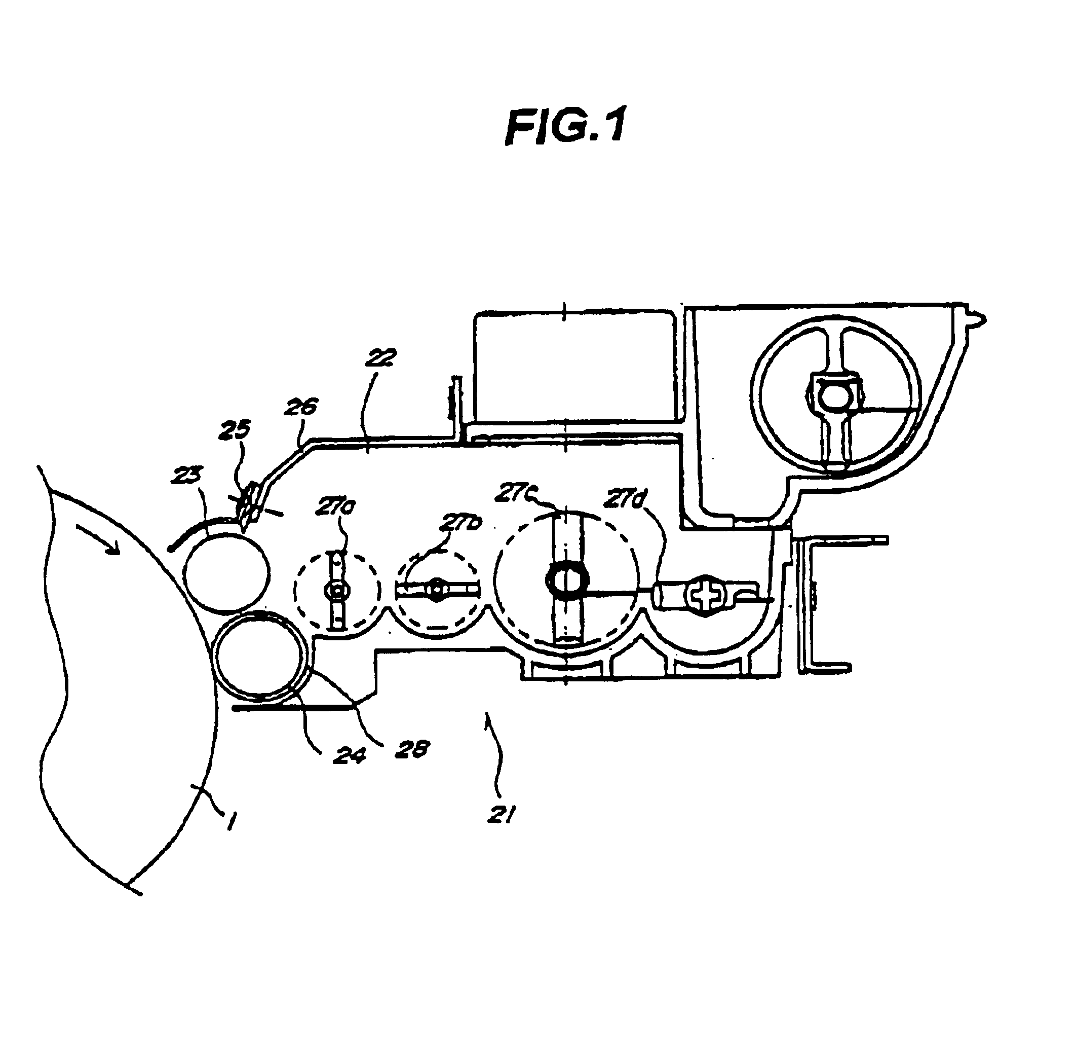
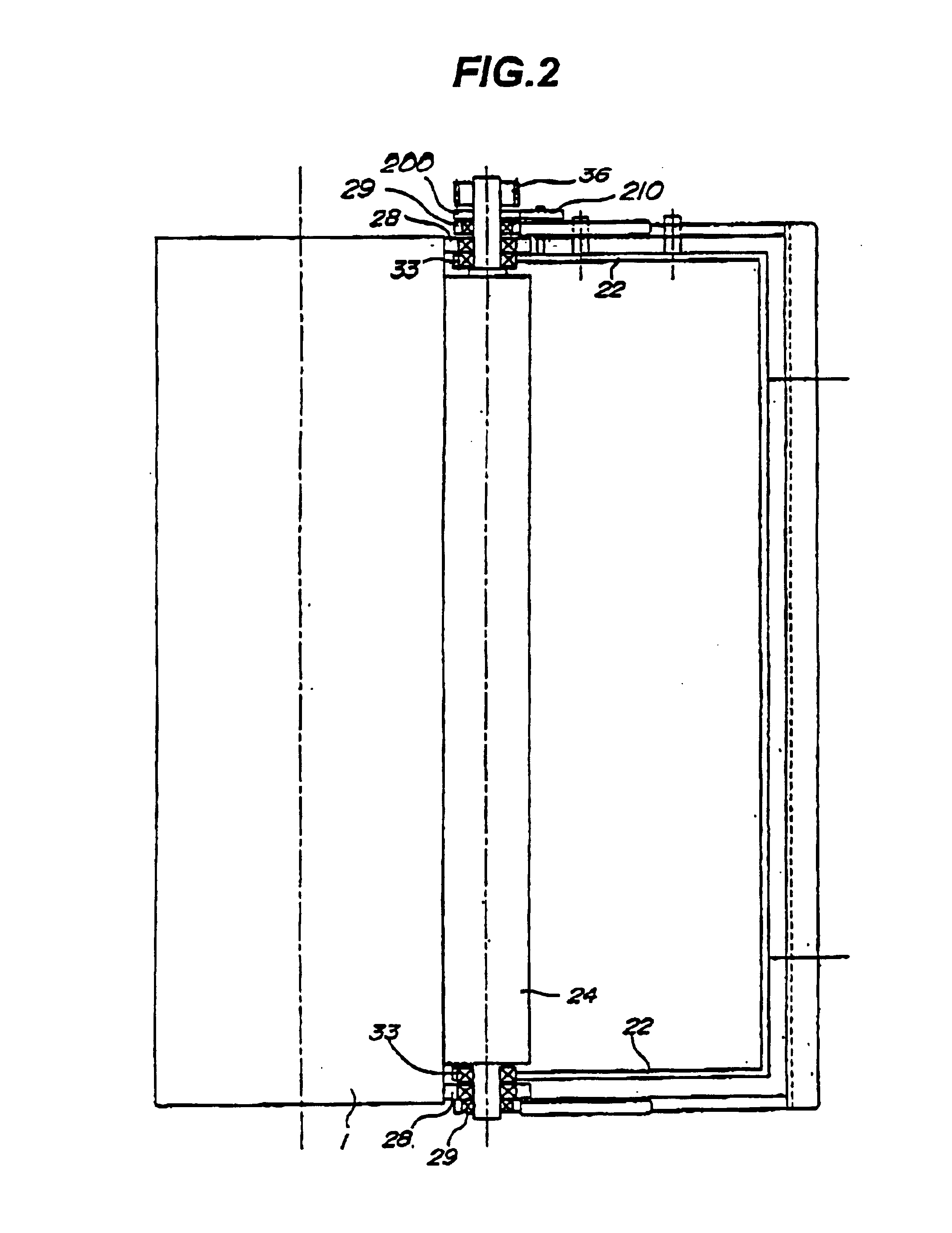
The present invention relates to a developing apparatus comprisinga developing container for containing a developing agent and rotatable first and second developing members provided at the developing container as to face an image carrier for developing an electrostatic image formed on the image carrier. The first developing member is secured to the developing container to keep a gap to the image carrier and the second developing member has keeping members at both ends in a longitudinal direction thereof to keep a gap to the image carrier.

Description

BACKGROUND OF THE INVENTION1. Field of the InventionThis invention relates to a developing apparatus for photocopiers, printers, facsimile machines, and the like which uses one of an electrophotographic method, an electrostatic recording method, and the like.2. Description of Related ArtFIG. 9 is a cross section showing a schematic structure of a conventional image forming section. In the image forming section such as a photocopier shown in FIG. 9, a photosensitive body 101 as an image carrier is charged with a charging apparatus 102, and an electrostatic latent image is formed on a circumferential surface of the photosensitive body 101 by exposing images of the original document at an exposure position 103 with an exposure optical system. The electrostatic latent image formed on a circumferential surface of the photosensitive body is developed by a developing apparatus 109 to form a toner image, and the toner image is transferred onto a transfer material in application of a voltage...

Claims


Application Information

Patent Timeline
Patent Type & Authority Patents(United States)
IPC IPC(8): G03G15/08G03G15/00
CPCG03G15/0813G03G2215/0648
Inventor SUGIYAMA, SHINICHI
Owner CANON KK
Why Eureka
Try Eureka