Lithographic apparatus, device manufacturing method, and device manufactured thereby

a technology of lithographic projection and manufacturing method, which is applied in the direction of electrical equipment, printers, instruments, etc., can solve the problems of image errors and increase, and achieve the effects of reducing the cooling amount, reducing the heating of the mirror shield, and reducing the heating coefficien

Active Publication Date: 2005-01-27
ASML NETHERLANDS BV
View PDF8 Cites 43 Cited by
  • Summary
  • Abstract
  • Description
  • Claims
  • Application Information

AI Technical Summary

Benefits of technology

[0026] The mirror shield absorbs heat radiation generated by heating due to beam reflection losses. By using mirror shields for individual mirrors the amount of cooling is minimized as well as effects on the support of the mirrors. The mirror shield may face at least a back surface of the mirror, but may also be shaped so that it also faces sides of the mirror between the front and the back surface of the mirror, and even may be shaped to face a part of the front surface on which the projection beam is not incident.
[0027] The surface of the mirror heat shield that faces the mirror may have a higher absorption coefficient than the surface that faces away from the mirror. Thus, heating of the mirror shield is reduced, which may be desirable if, due to space limitations, only small heat transfer capacity is available for a mirror. Alternatively a high absorption coefficient (>0.8) may be used on the surface of the mirror shield facing away from the mirror, to prevent reflection of heat radiation towards other mirrors or the support structure.
[0028] In another embodiment the heat shields include an inner heat shield that covers

Problems solved by technology

However, this type of heat transport, when applied to the projection system of a lithographic projection apparatus, may lead to mechanical vibrations that resu

Method used


Image

  • Lithographic apparatus, device manufacturing method, and device manufactured thereby
  • Lithographic apparatus, device manufacturing method, and device manufactured thereby
  • Lithographic apparatus, device manufacturing method, and device manufactured thereby

Examples


Embodiment Construction

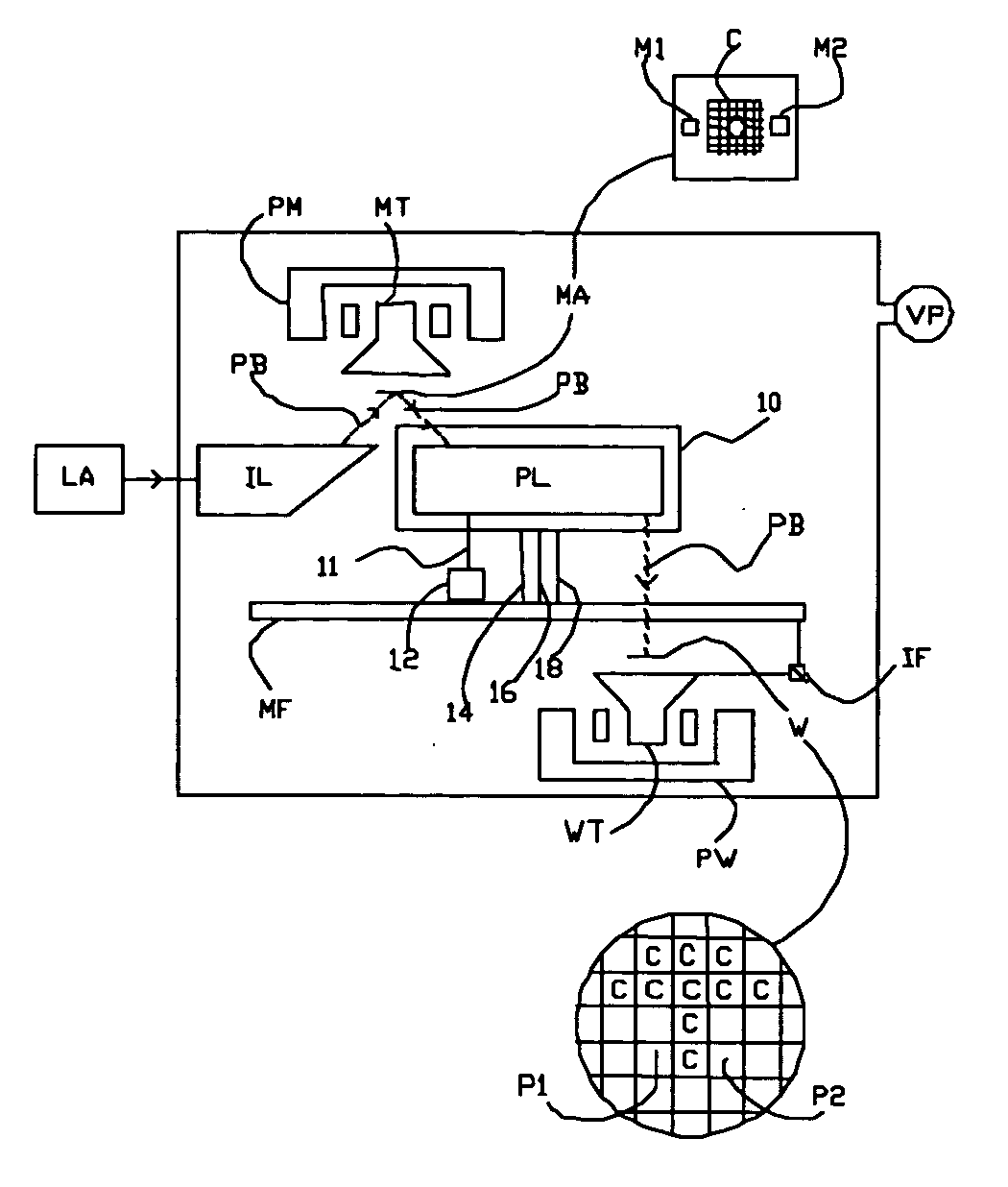
[0040]FIG. 1 schematically depicts a lithographic projection apparatus 1 according to an embodiment of the invention and including a radiation system LA, IL configured to supply a beam PB of radiation (e.g. EUV radiation). In this emobidment, the radiation system also includes a radiation source LA; a first object table (mask table) MT provided with a mask holder configured to hold a patterning device, illustrated in the form of a mask MA (e.g. a reticle), and connected to a first positioning device PM that accurately positions the mask with respect to a projection system (“lens”) PL. A second object table (substrate table) WT is provided with a substrate holder is configured to hold a substrate W (e.g. a resist-coated silicon wafer) and is connected to a second positioning device PW that accurately positions the substrate with respect to the projection system PL. The projection system (“lens”) PL (e.g. a set of mirrors) is configured to image an irradiated portion of the mask MA on...


PUM


Abstract

A lithographic projection apparatus contains a projection system configured to project a patterned beam of radiation onto a target portion of a substrate. The projection system contains one or more optically active mirrors and heat shields located to intercept heat radiation to or from the mirrors and/or their support. The heat shields are actively cooled and the mirrors and the heat shields and the mirrors are supported separately on a support frame to reduce vibration of the mirrors due to active cooling. The heat shields may include heat shields that intercept heat radiation to or from the support and/or respective heat shields for individual mirrors that intercept heat radiation to or from the mirrors.

Description

[0001] This application claims priority to European Patent Application 03076433.6, filed May 13, 2003, the contents of which are incorporated by reference. [0002] 1. Field of the Invention [0003] The present invention relates to a lithographic projection apparatus, a device manufacturing method and a device manufactured thereby, including a radiation system for supplying a projection beam of radiation; a support arrangement for supporting patterning devices, the patterning devices serving to pattern the projection beam according to a desired pattern; a substrate table for holding a substrate; and a projection system for projecting the patterned beam onto a target portion of the substrate. [0004] 2. Description of the Related Art [0005] The term “patterning devices” as here employed should be broadly interpreted as referring to a device that can be used to endow an incoming radiation beam with a patterned cross-section, corresponding to a pattern that is to be created in a target por...

Claims


Application Information

Patent Timeline
IPC IPC(8): G21K1/06G02B7/182G03F7/20H01L21/027
CPCG03F7/70808G03F7/70825G03F7/70833G03F7/70991G03F7/70891G03F7/709G03F7/70858G03F7/20
Inventor BOX, WILHELMUS JOSEPHUSVAN DIJSSELDONK, ANTONIUS JOHANNES JOSEPHUSFRANKEN, DOMINICUS JACOBUS PETRUS ADRIANUSLEENDERS, MARTINUS HENDRIKUS ANTONIUSLOOPSTRA, ERIK ROELOFSMITS, JOSEPHUS JACOBUSVAN DER WIJST, MARC WILHELMUS MARIA
Owner ASML NETHERLANDS BV
Why Eureka
Try Eureka