Method for manufacturing a suspension

a technology of suspension and rib, which is applied in the direction of head support, record information storage, instruments, etc., can solve the problems of inability to meet the needs of bending tools during ribs, inconvenient assembly, and inability to meet the needs of bending tools, etc., to achieve convenient positioning, less deformation, and high speed and accuracy.

Active Publication Date: 2012-04-24
NHK SPRING CO LTD
View PDF4 Cites 43 Cited by
  • Summary
  • Abstract
  • Description
  • Claims
  • Application Information

AI Technical Summary

Benefits of technology

[0016]Accordingly, the object of the present invention is to provide a load beam having stable properties such that it is less deformed by a damper affixed thereto, a suspension, and a manufacturing method for the suspension.
[0022]The recess is formed by, for example, partial etching. Since the recess formed by partial etching can be used as a guide for the affixture of the damper, the damper can be easily positioned with respect to the load beam.
[0023]Since the damper can be affixed to the unbent flat load beam, moreover, the operation for affixing the damper can be easily automated. Since the damper can be affixed to each load beam of the continuous load beam blank that comprises a plurality of unbent load beams, in particular, the damper affixing operation can be automated with higher speed and accuracy and less deformation. In this case, the efficiency of the damper affixing operation can be further improved.
[0024]As the damper is pressed against and affixed to the load beam, a part of its viscoelastic member may sometimes be caused to project from the periphery of the restrainer. According to the present invention, however, the damper is contained in the recess, so that the projecting part of the viscoelastic member can be confined within a groove defined between the inner side surface of the recess and the side surface of the damper. Thus, the viscoelastic member can be prevented from projecting outside the load beam. Since the groove exists inside the recess, moreover, a coating material (e.g., resin) can be easily filled around the damper, and the usage of the coating material can be reduced.
[0025]Thus, according to the present invention, the damper is contained in the recess formed in the load beam. The weight of the load beam itself can be reduced by a margin corresponding to the recess. Consequently, an increase in weight attributable to the presence of the damper can be compensated with a reduction of the weight of the load beam, so that the suspension can be made lighter in weight.

Problems solved by technology

This results in a read or write error.
If the damper 14 is affixed to the load beam 10 before this load bending, it may undesirably interfere with bending tool during the rib or load bending.
Variations of these properties impair the commodity value and working properties of the suspension.
If the damper is dislocated with respect to the load beam when it is affixed to the load beam, moreover, it may adversely affect the properties of the suspension.
Conventionally, it is difficult to accurately position the damper, since the damper is affixed to the load beam formed of a flat thin-plate spring that carries no indication of a damper mounting position.
Since one damper 14 is affixed to each load beam 10, furthermore, the affixing operation is time-consuming, that is, work performance is poor.
In such a case, it is troublesome and difficult to thoroughly remove a projecting part of the viscoelastic member.
In these cases, the usage of the coating material is too much to reduce the weight of the load beam.

Method used


Image

  • Method for manufacturing a suspension
  • Method for manufacturing a suspension
  • Method for manufacturing a suspension

Examples


Embodiment Construction

[0054]One embodiment of the present invention will now be described with reference to the accompanying drawings.

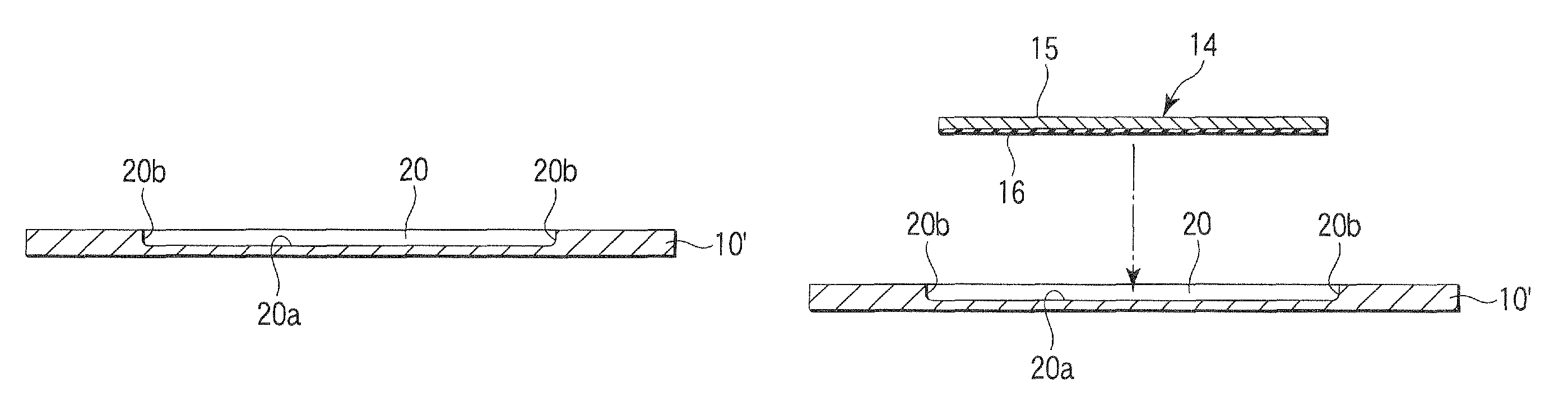
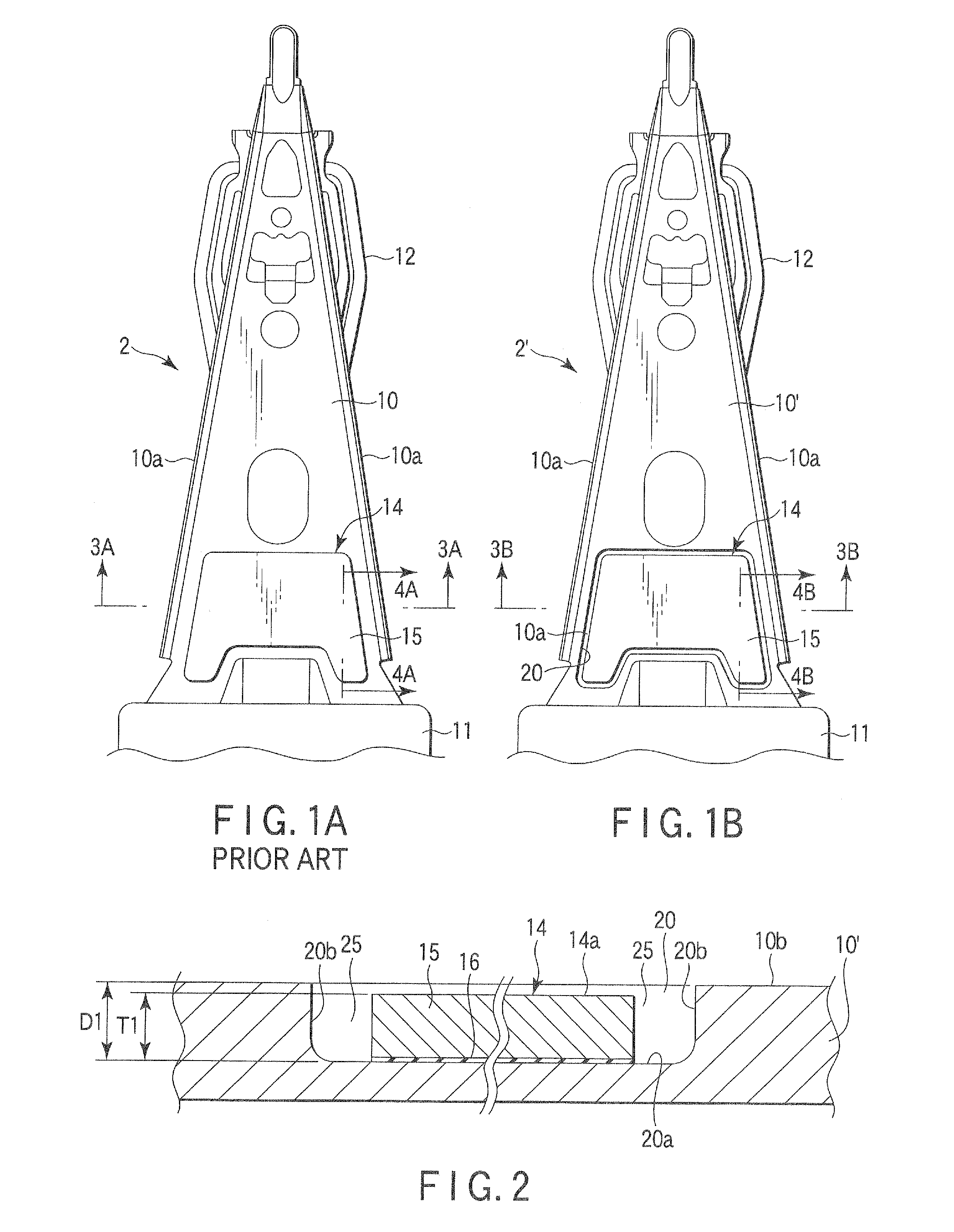
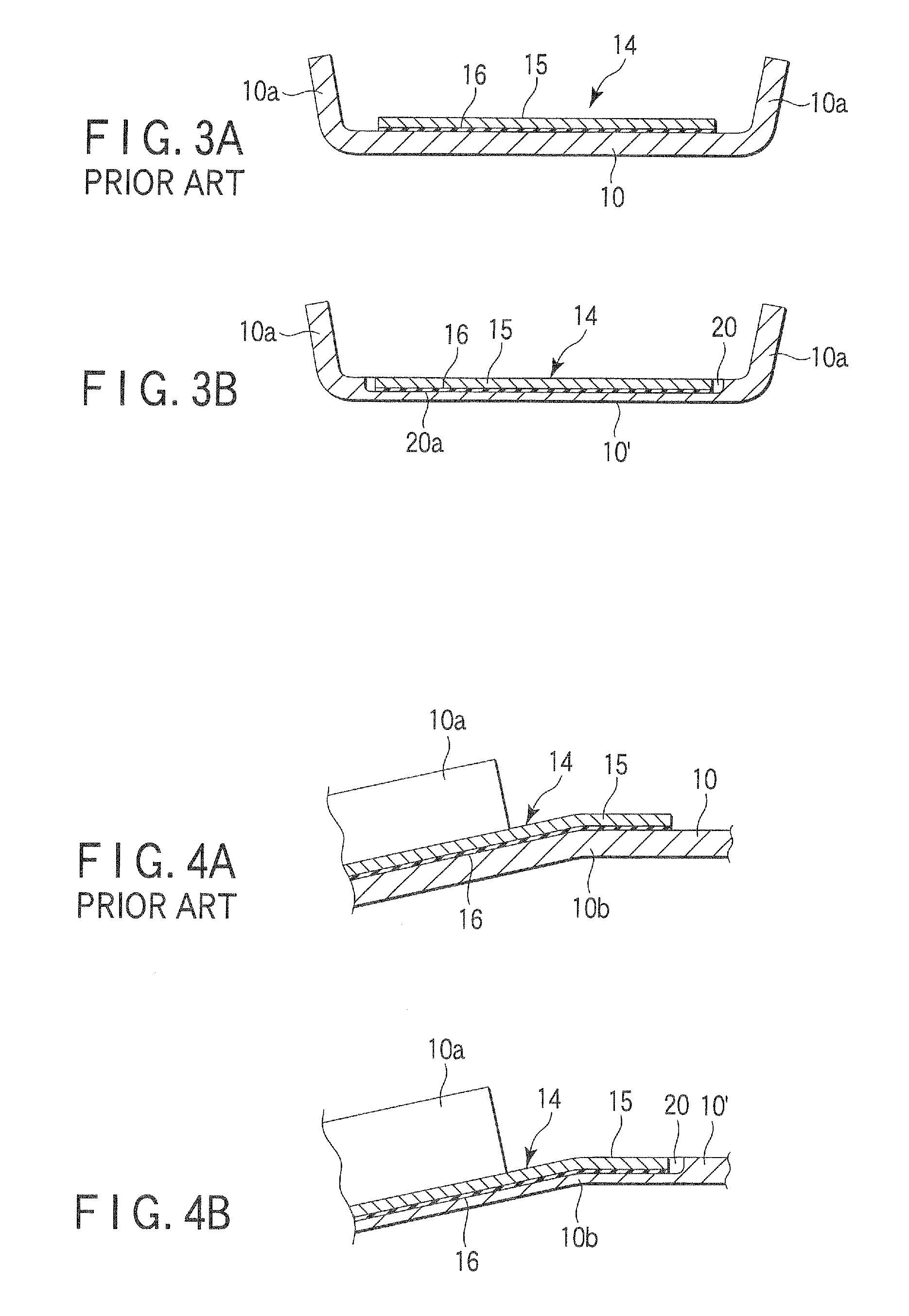
[0055]FIG. 1A is a plan view of the suspension 2 comprising the conventional load beam 10. FIG. 15 is a plan view of a suspension 2′ comprising a load beam 10′ according to the invention. FIG. 2 is a sectional view typically showing the load beam 10′ and a damper 14 according to the invention. A recess 20 is formed in a part of the load beam 10′. FIG. 3A is an enlarged sectional view taken along line 3A-3A of FIG. 1A. FIG. 3B is an enlarged sectional view taken along line 3B-3B of FIG. 1B. FIG. 4A is an enlarged sectional view taken along line 4A-4A of FIG. 1A. FIG. 4B is an enlarged sectional view taken along line 4B-4B of FIG. 1B.

[0056]The load beam 10 shown in FIG. 3A is bent so that its transversely opposite side edge portions 10a rise like ribs. A central part of the conventional load beam 10 has a flat surface. In the load beam 10 shown in FIG. 4A, the proximal porti...


PUM

PropertyMeasurementUnit
thicknessaaaaaaaaaa
speedaaaaaaaaaa
recording densitiesaaaaaaaaaa

Abstract

A suspension for supporting a magnetic head is provided with a load beam formed of a thin-plate spring. A recess for accommodating a damper is formed in the load beam. The damper is affixed to a bottom surface of the recess.

Description

CROSS-REFERENCE TO RELATED APPLICATIONS[0001]This application is based upon and claims the benefit of priority from prior Chinese Patent Application No. 200910006550.3, filed Feb. 17, 2009, the entire contents of which are incorporated herein by reference.BACKGROUND OF THE INVENTION[0002]1. Field of the Invention[0003]The present invention relates to a load beam constituting a part of a suspension of a disk drive, suspension with the load beam, and a manufacturing method for the suspension.[0004]2. Description of the Related Art[0005]Conventionally, a magnetic disk device, such as a hard disk drive (HDD) or magneto-optical drive, comprises a magnetic head. The head flies above a magnetic disk rotating at high speed with a fine space therebetween. Data on the disk is read or written by the head.[0006]An example of a suspension is disclosed in, for example, Jpn. Pat. Appln. KOKAI Publication No. 10-162532 or 9-91909.[0007]In recent years, the head size and flying height (above the dis...

Claims


Application Information

Patent Timeline
Patent Type & Authority Patents(United States)
IPC IPC(8): G11B5/127H04R31/00
CPCG11B5/4833Y10T29/49032Y10T29/49025Y10T29/4903Y10T29/49027
Inventor IKEJI, YOICHI
Owner NHK SPRING CO LTD
Why Eureka
Try Eureka