Engine stop control system for hybrid electric vehicle

Active Publication Date: 2012-12-06
NISSAN MOTOR CO LTD
View PDF3 Cites 42 Cited by
  • Summary
  • Abstract
  • Description
  • Claims
  • Application Information

AI Technical Summary

Benefits of technology

[0013]As described herein, by performing the engine stopping crank angle control without disconnecting the motor/generator from driving wheels, the above described deterioration in energy recovery efficiency may be a

Problems solved by technology

However, in this engine stop control strategy, the engine lowers its rotation speed by the friction of the engine itself to finally come to stop with the first clutch released.
Consequently, it is impossible to stop the engine at a specified crank angle position, but rather the stop position is left to take its course of nature and thus unpredictable.
Therefore, in existing systems for engine s

Method used


Image

  • Engine stop control system for hybrid electric vehicle
  • Engine stop control system for hybrid electric vehicle
  • Engine stop control system for hybrid electric vehicle

Examples


Embodiment Construction

[0029]In the following, an explanation of an embodiment according to the present invention will be made with reference to accompanying drawings.

[0030]Hybrid Vehicle Powertrain.

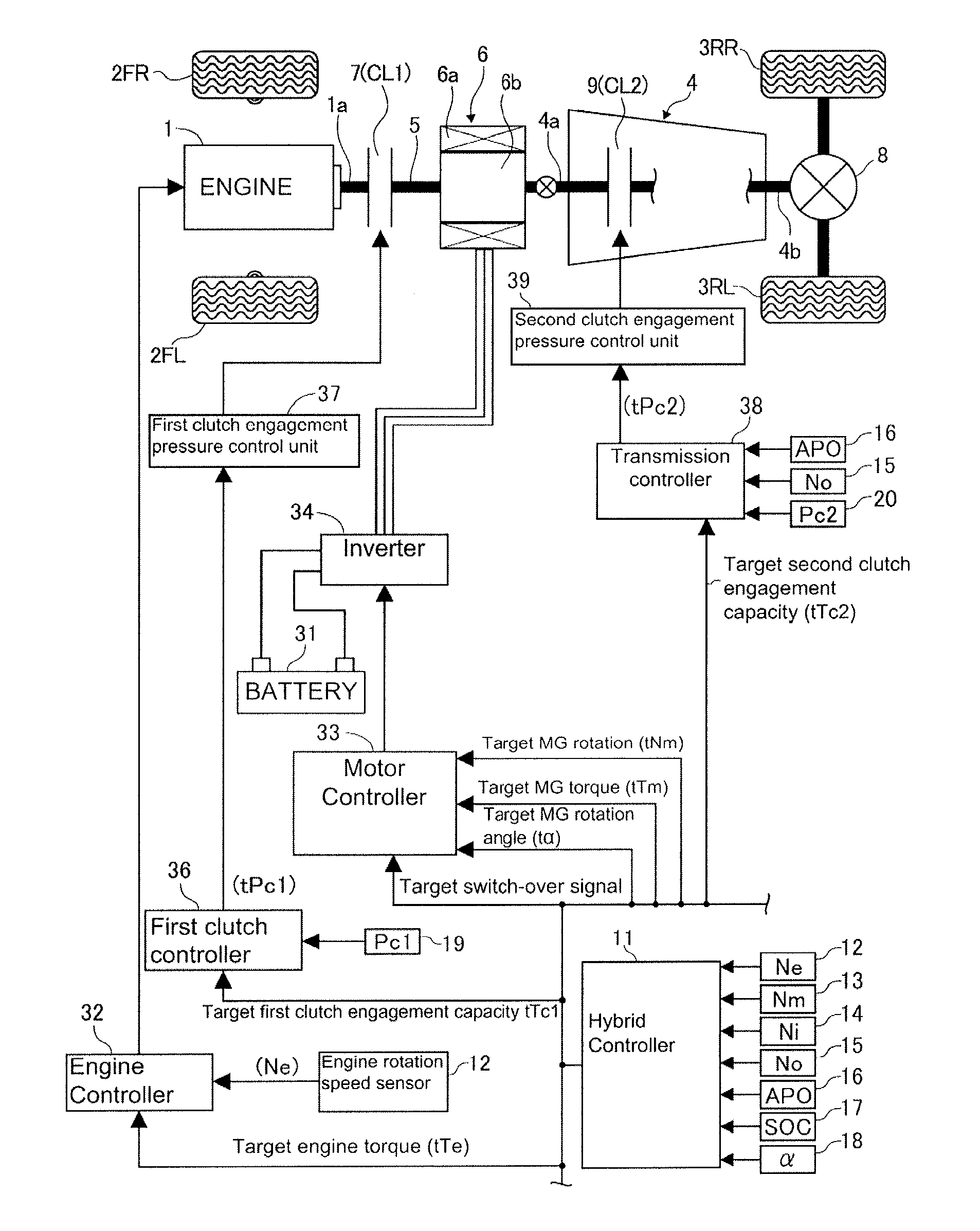
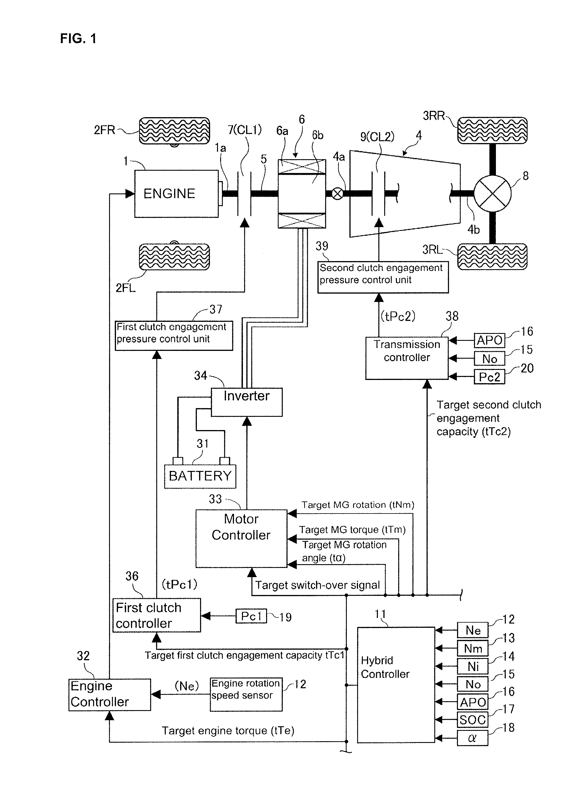
[0031]FIG. 1 shows a powertrain for a hybrid vehicle with an engine stop control system according to the embodiment described herein. This HEV is obtained by doing alterations on a conventional front engine, rear wheel drive vehicle (FR vehicle) as a base platform to obtain a HEV. In some prior systems, an engine is denoted as a power source, 2FL and 2FR denote left front wheel and right front wheel, respectively, i.e., left and right driven wheels, 3RL, 3RR denotes a left rear wheel and right rear wheel (left right driving wheels), respectively.

[0032]In the hybrid vehicle powertrain shown in FIG. 1, as in conventional rear-wheel drive vehicles, an automatic transmission 4 is arranged in a tandem configuration behind an engine 1 with respect to the vehicle longitudinal direction such that the rotation of engin...


PUM


Abstract

An engine stop control system for a hybrid electric vehicle including a powertrain having an engine, an electric motor/generator, and driving wheels, including a first clutch coupling the engine to the motor/generator, a second clutch coupling the motor/generator to the driving wheels, a controller configured to select between two driving modes of the vehicle by controlling engagement and disengagement of the first clutch and the second clutch so that the vehicle may be driven either solely by the motor/generator or a combination of the engine and the motor/generator, and to control the stop position of the engine to be a desired stop position by controlling the rotation speed of the motor/generator while the first clutch in complete engagement and the second clutch in a slip state.

Description

CROSS-REFERENCE TO RELATED APPLICATIONS [0001]This application claims priority under 35 U.S.C. §119 to Japanese Patent Application No. 2011-1201798, filed on May 30, 2011, which is incorporated by reference herein in its entirety.BACKGROUND OF THE INVENTION[0002]1. Field of Invention[0003]The present invention relates to an engine stop control system for a hybrid electric vehicle (HEV). The vehicle has a power train comprised of an engine, a first clutch, a motor / generator, a second clutch, and driving wheels arranged in this order as a torque transmission path The vehicle has two driving modes by selectively controlling an engagement or release of the first and second clutches so that the vehicle may be either electrically driven by the motor / generator only, or may be driven by both the engine and the motor / generator under a hybrid mode.[0004]2. Description of Related Art[0005]In a conventional hybrid vehicle of this type, a so-called one-motor, two-clutch, parallel hybrid vehicle ...

Claims


Application Information

Patent Timeline
IPC IPC(8): B60W20/00B60W10/06B60W10/08B60W10/02B60L50/16
CPCB60K6/48Y10T477/26B60W10/06B60W10/08B60W20/00B60W20/40B60W30/18127B60W30/192B60W2510/0685B60W2710/021B60W2710/025Y02T10/48B60K2006/4825Y02T10/6286Y02T10/6221Y02T10/6252Y02T10/92B60W10/02Y02T10/40Y02T10/62
Inventor NOZAKI, MIKIO
Owner NISSAN MOTOR CO LTD
Why Eureka
Try Eureka