Steering device for motor vehicle

a steering device and motor vehicle technology, applied in the direction of mechanical control devices, couplings, instruments, etc., can solve the problems of difficult transmission of unpleasant vibration or sound onto the steering wheel, insufficient function, and insufficient abrasion resistance of plastic products

Active Publication Date: 2006-07-27
NSK LTD +1
View PDF61 Cites 43 Cited by
  • Summary
  • Abstract
  • Description
  • Claims
  • Application Information

AI Technical Summary

Benefits of technology

[0051] The intermediate shaft is extended and contracted easily at tilt and telescopic operations so that it is possible to obtain an optimal position for the driver and to obtain a stable steering property.

Problems solved by technology

However, in terms of the steering stability, the assembling performance and the cost, these functions are not always sufficient.
At running of the vehicle, the intermediate shaft is to absorb a vibration and a displacement from the steering gear side so as to make it difficult to transmit unpleasant vibration or sound onto the steering wheel.
However, plastic products are not satisfactorily abrasion-proof and it is difficult to maintain the performance of such products without backlash for a long term use.
For this reason, when abrasion is produced, there arises a problem that the backlash is generated on the steering shaft.
Since the structure is also required to allow relative movement in the axial direction so that the male shaft and the female shaft are moved relatively to each other, it is required to provide a gap in a sliding portion so that backlash can not be structurally prevented completely.
In these structures, since leaf springs having different curvatures are provided in grooves of the male shaft and the female shaft having the curvatures, it is very difficult to obtain a large amount of flexure of the leaf springs.
As a result, it is very difficult to provide the leaf springs with a flexural amount which can allow fluctuations in the processing precision of the male shaft and the female shaft.
When torque is inputted, the male shaft, the leaf springs, balls and the female shaft are mutually contracted to transmit the torque, so that the points contacting with the balls have very high surface pressure, and the steering shaft can highly possibly not satisfy the required torque transmitting performance and the life as that used for a vehicle (particularly when the shaft is combined with the column-assist type electric power steering which is required to transmit high torque).
Since an outer leaf spring tends to slide sideways with respect to the female shaft at the time of torque transmission and hysteresis is easily generated, a structural problem that the magnitude of this hysteresis can not be controlled.
As a result, it is difficult to obtain a steering system having such an excellent performance as to satisfy the items described above.
At running of the vehicle, the intermediate shaft is to absorb a vibration and a displacement from the steering gear side so as to make it difficult to transmit unpleasant vibration or sound onto the steering wheel.

Method used


Image

  • Steering device for motor vehicle
  • Steering device for motor vehicle
  • Steering device for motor vehicle

Examples


first embodiment

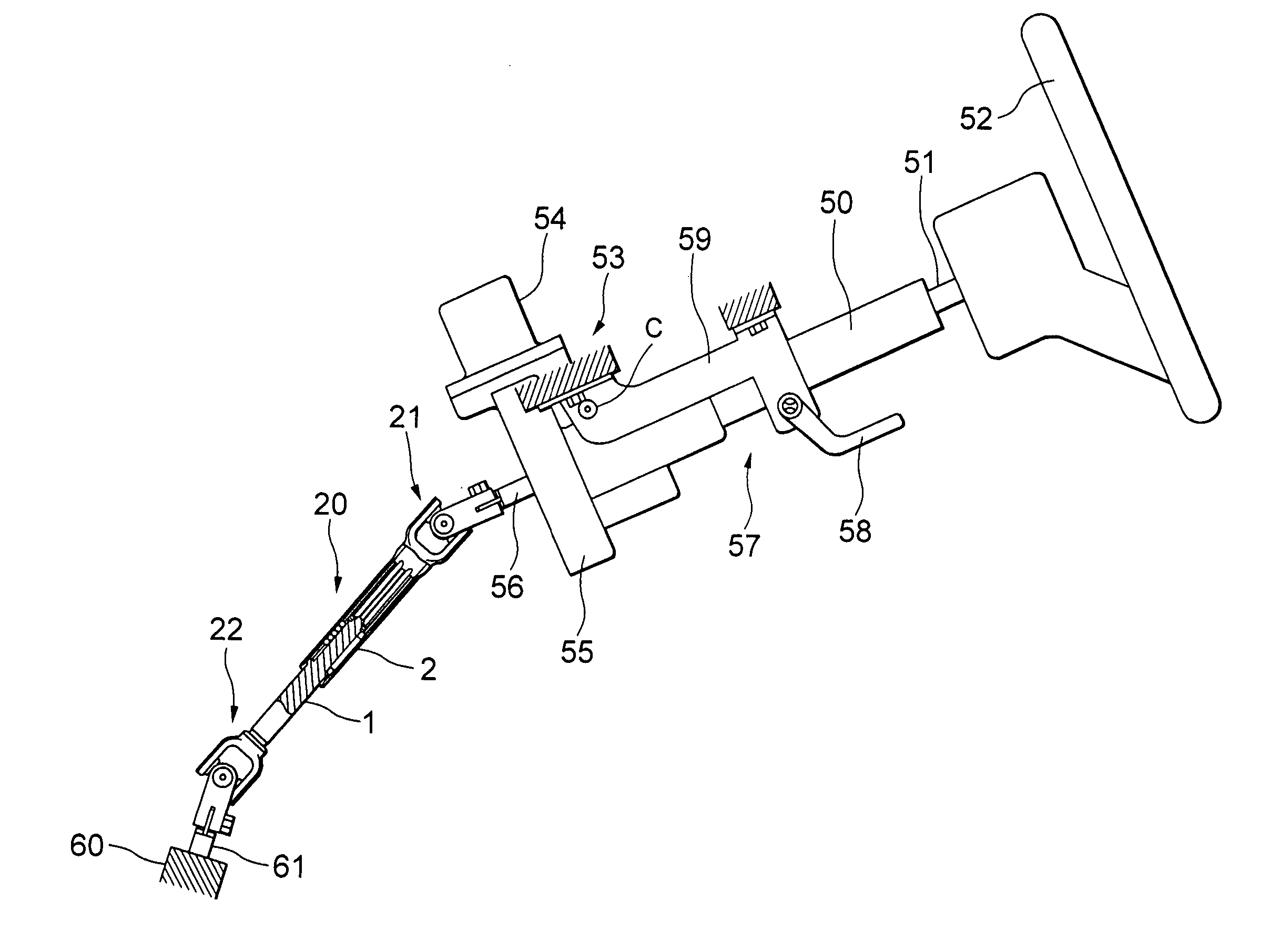
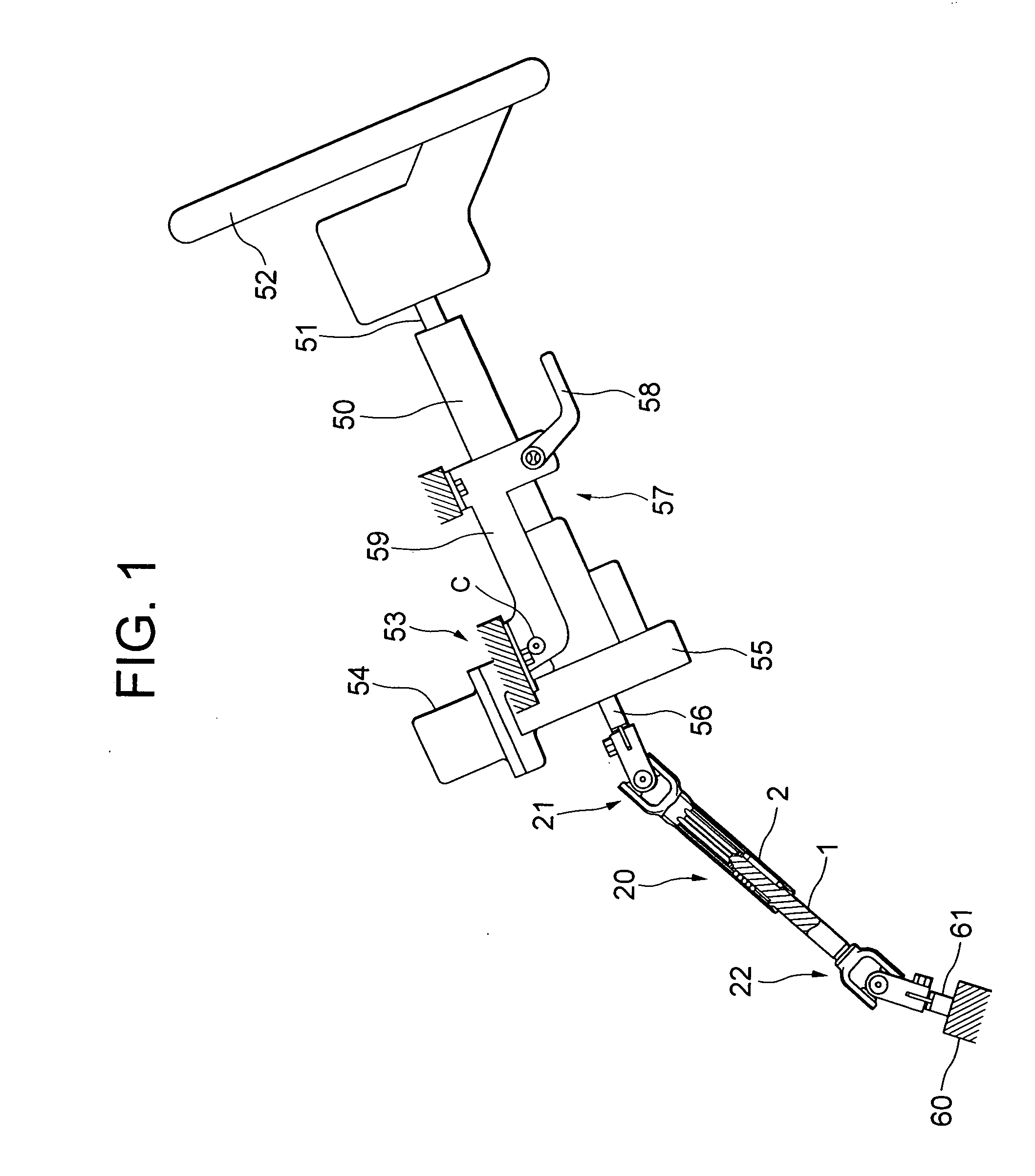
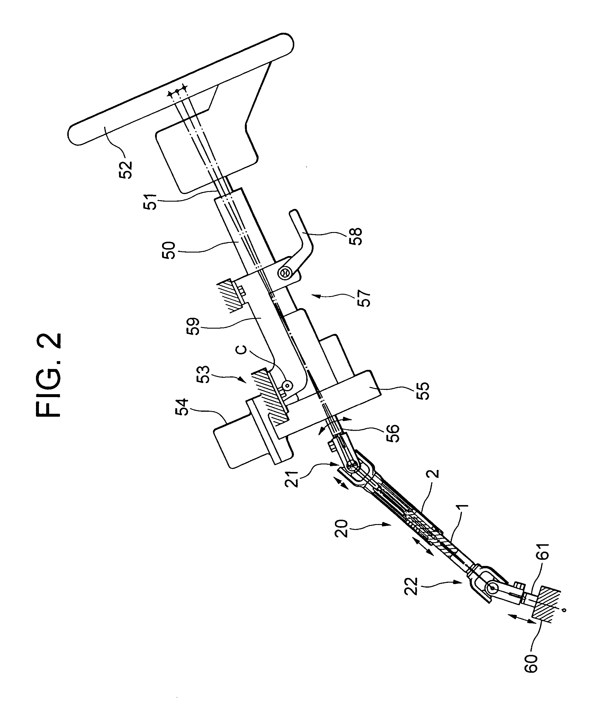
[0065]FIG. 1 is a schematic view of a steering apparatus for a vehicle according to the first embodiment of the present invention, and FIG. 2 is a schematic view of the steering apparatus for a vehicle shown in FIG. 1, for showing the highest level and the lowest level of tilting and for explaining various axial displacements.

[0066] A steering shaft 51 is rotatably supported by a steering column 50, and a steering wheel 52 is provided in an upper part of the steering shaft 51.

[0067] The steering column 50 is provided with a column-assist type electric power steering apparatus 53, and this electric power steering apparatus 53 is provided with an electric motor 54 for assist, a gear unit 55 serving as a reduction gear, an output shaft 56 for outputting a steering power assisted by the electric motor 54 with high torque, and so on.

[0068] The steering column 50 is also provided with a tilt mechanism 57. When an operation lever 58 is operated, the steering column 50 can be tilt-adjust...

second embodiment

[0123]FIG. 6 is a schematic view of a steering apparatus for a vehicle according to the second embodiment of the present invention. FIG. 7 is a schematic view of the steering apparatus for a vehicle shown in FIG. 6, for showing a state that it is telescopically sliding. FIG. 8 is a view only for showing the center line of FIG. 7, in a state that an intermediate shaft is extended and contracted by the telescopic sliding.

[0124] The second embodiment has a column structure which is provided with a telescopic function, in addition to a tilt function, so that the whole steering column 50 can move in the axial direction. In such a case, the intermediate shaft 20 is required to be extended and contracted freely.

[0125] As shown in FIG. 6, an elongated hole 31 for telescopic operation is formed on a bracket 59 which is fixed to the vehicle body side, and another elongated hole 33 for telescopic operation is formed on a distance bracket 32 which is provided on the steering column 50.

[0126]...


PUM


Abstract

There is disclosed a steering apparatus for a vehicle in which a steering power of a steering shaft is assisted by a column-assist type electric power steering apparatus so that the steering power is transmitted to steer the wheels by means of a steering mechanism, in which a telescopic shaft with a male shaft and a female shaft fitted to each other to be mutually unrotatable and slidable is interposed between an output shaft of said column-assist type electric power steering apparatus and an input shaft of the steering mechanism.

Description

TECHNICAL FIELD [0001] The present invention relates to a steering apparatus for a vehicle in which a steering power of a steering shaft is assisted by a column-assist type electric power steering apparatus so that the steering power having increased torque is transmitted through a telescopic intermediate shaft to steer the wheels by means of a steering mechanism in its turn. BACKGROUND ART [0002] In Japanese Utility Model Application Laid-Open No. 1-145670, an intermediate shaft is interposed between an output shaft of a column-assist type electric power steering apparatus and a pinion shaft of a steering gear. This intermediate shaft is provided with a damper for damping a reaction force from a road surface. This intermediate shaft, however, is not extended and / or contracted in the axial direction. [0003] FIGS. 9 to 12 show a steering apparatus for a vehicle according to a prior art. According to the prior art, an intermediate shaft which is collapsible at a secondary collision is...

Claims


Application Information

Patent Timeline
Patent Type & Authority Applications(United States)
IPC IPC(8): B62D5/04B62D1/18B62D1/20B62D1/185F16C3/03F16C3/035F16D3/06
CPCB62D1/185B62D1/20F16C3/035Y10T74/20834F16C29/123F16C2326/24F16D3/065F16D2300/22
Inventor YAMADA, YASUHISA
Owner NSK LTD
Why Eureka
Try Eureka