Mounting system for an air intake manifold assembly

a technology for mounting systems and intake manifolds, which is applied in the direction of air intakes for fuel, combustion-air/fuel-air treatment, machines/engines, etc. it can solve the problems of increasing the cost and complexity of the manifold, consuming an excessive amount of the limited space of the intake manifold, and labor-intensive use of fasteners. to achieve the effect of reducing the cos

Inactive Publication Date: 2005-01-11
HARVEY HLDG
View PDF19 Cites 7 Cited by
  • Summary
  • Abstract
  • Description
  • Claims
  • Application Information

AI Technical Summary

Benefits of technology

Applicant has discovered that in the particular manifold assembly structure disclosed herein, typical fasteners could not be used on a “near” side to join the upper and lower body parts together because the associate runner tracks were too close together. Even in constructions where typical fasteners could be used, the present invention could reduce the cost associated with joining the body parts together using conventional fasteners. In accordance with the mounting system of this invention, the lower and upper parts of the manifold assembly are sealed using notches to cause a tight condition on a first or near side and using fasteners to draw down an opposite second

Problems solved by technology

Typically, the sections are joined together with bolts and a gasket or other suitable hardware to complete the manifold, further adding to the cost and co

Method used


Image

  • Mounting system for an air intake manifold assembly
  • Mounting system for an air intake manifold assembly
  • Mounting system for an air intake manifold assembly

Examples


first embodiment

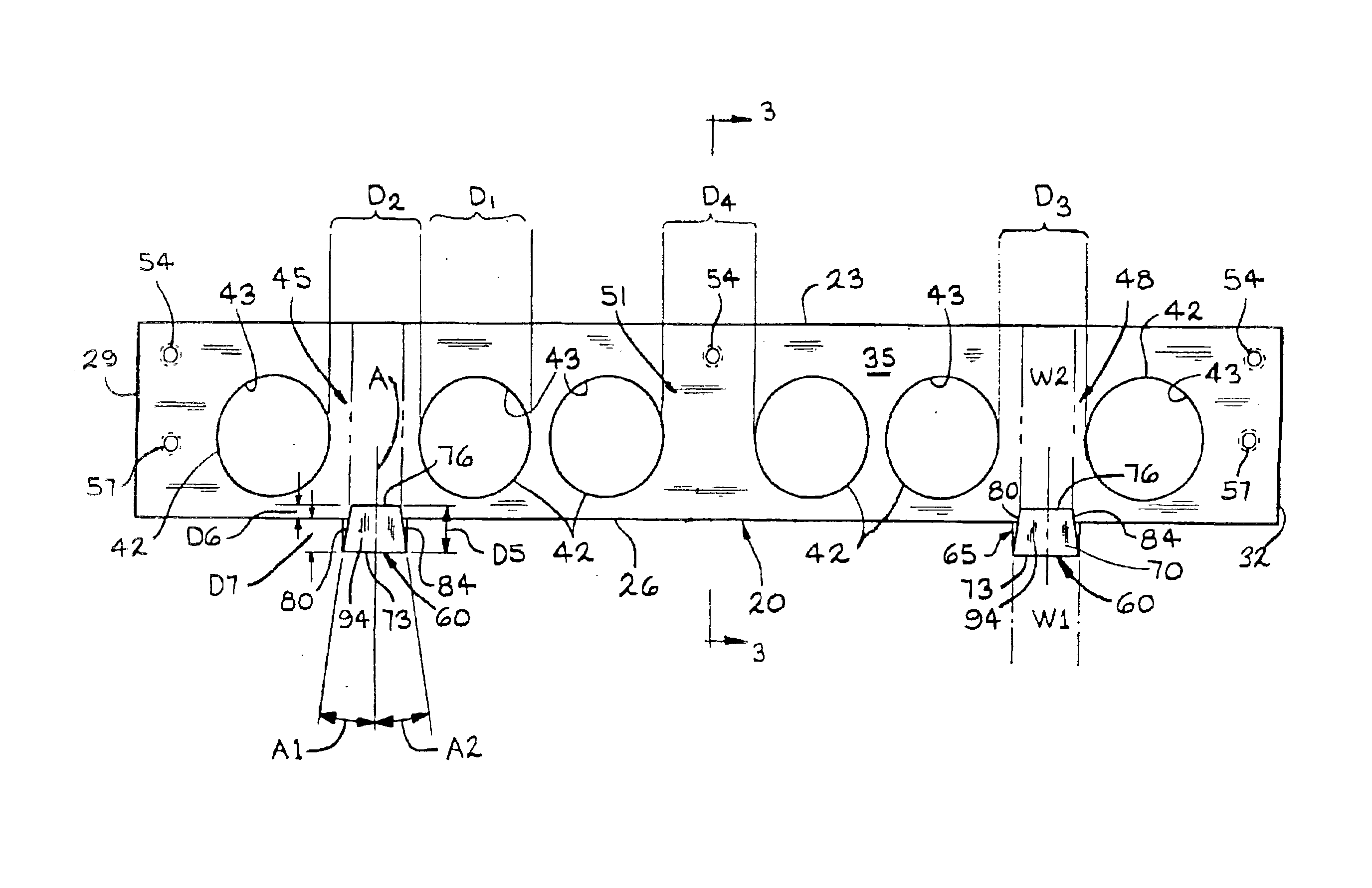
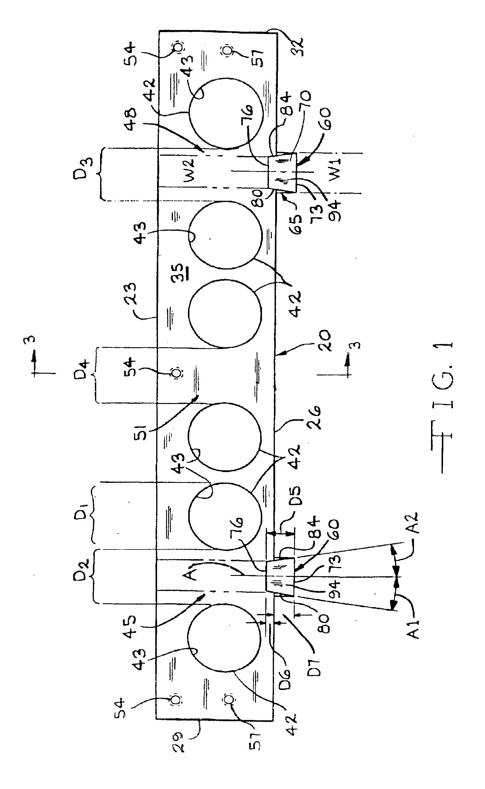
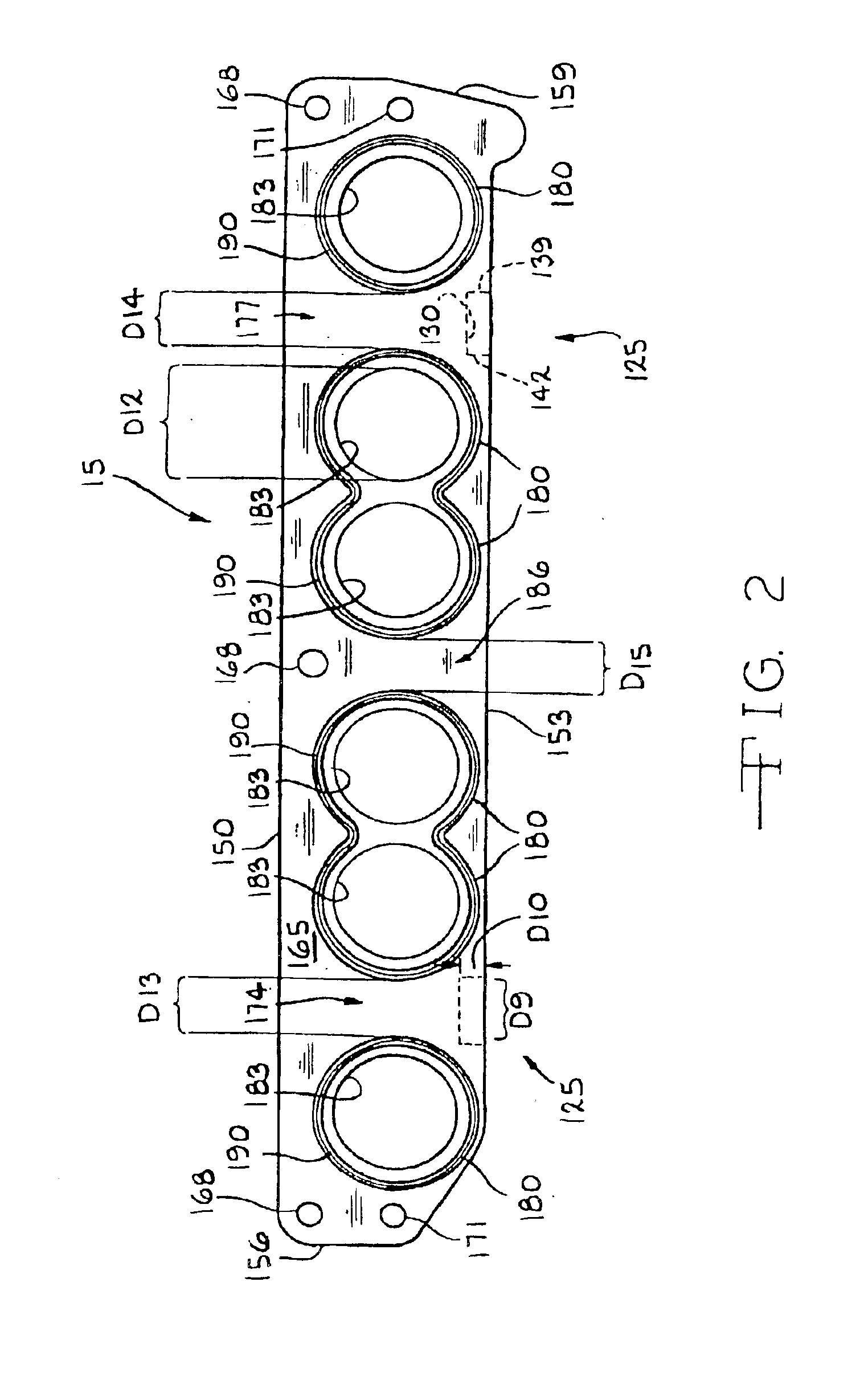
Referring now to the drawing, there is illustrated in FIG. 3 an air intake manifold assembly, indicated generally at 10, including the mounting system in accordance with the present invention. For purposes of clarity in presentation, only those portions of the air intake manifold assembly 10 that are necessary for a complete understanding of this invention will be described. As illustrated in FIG. 3, the air intake manifold assembly 10 includes an upper body part or manifold 15 (best shown in FIG. 2), and a lower body part or manifold 20 (best shown in FIG. 1), operatively joined together in accordance with the mounting system of the present invention.

Referring now to FIG. 1, the lower body part 20, generally referred to as a mounting flange, is constructed from a suitable material, such as for example, plastic or aluminum. The lower body part 20 includes a pair of opposed side walls 23 and 26, and a pair of opposed end walls 29 and 32. The side walls 23 and 26 extend generally para...

second embodiment

Referring now to the drawings, there is illustrated in FIGS. 4-6 an air intake manifold, indicated generally at 210, in accordance with the present invention. For purposes of clarity in presentation, only those portions of the air intake manifold assembly 210 that are necessary for a complete understanding of this invention will be described. As illustrated in FIG. 6, the air intake manifold assembly 210 includes an upper body part or manifold 215 and a lower body part or manifold 220 operatively joined together in accordance with the mounting system of the present invention.

The lower manifold 220 is constructed from a suitable material, such as for example, plastic or aluminum. The lower manifold 220 includes a pair of opposed side walls 223 and 226, and a pair of opposed end walls 229 and 232. The side walls 223 and 226 extend generally parallel to one another, and the end walls 229 and 232 extend generally parallel to one another and generally transverse relative to the side wall...


PUM

PropertyMeasurementUnit
Angleaaaaaaaaaa
Angleaaaaaaaaaa
Angleaaaaaaaaaa

Abstract

A mounting system for the air intake manifold assembly for attaching portions of an intake manifold. The system has an upper body part and a lower body part and is used for an internal combustion engine. The system includes a notch. The notch includes a lower surface and the notch is formed in the upper body part of the intake manifold. The system includes a mounting tab. The mounting tab includes a bottom wall. The mounting tab is formed in the lower body part of the intake manifold. A substantial portion of the lower surface of the notch and a substantial portion of the bottom wall of the mounting tab contact one another to couple the upper body part of the intake manifold and the lower body part of the intake manifold together.

Description

BACKGROUND OF THE INVENTIONThis invention relates in general to vehicle engines and in particular to an improved mounting system for an intake manifold assembly for use in such a vehicle engine.An intake manifold assembly of a multi-cylinder engine includes a plurality of branched air passageways or ducts. Each of the air passageways defines a generally tubular runner having an air intake port and an opposite air inlet port. The air intake port of the runner is joined to an associated plenum which supplies atmospheric, turbo, or supercharged air to the runner intake port, and the air inlet port is joined to a flange which is joined to an associated inlet port of each cylinder head of the engine to supply the air from the runner to each cylinder head. Conventional intake manifold assemblies are constructed of cast iron, magnesium, aluminum, and plastic.A typical aluminum intake manifold assembly is produced entirely by conventional casting process. These manifolds typically include a...

Claims


Application Information

Patent Timeline
IPC IPC(8): F02M35/10
CPCF02M35/10078F02M35/10144F02M35/10216F02M35/10222F02M35/112F02M35/10301F02M35/10321F02M35/10327F02M35/10354F02M35/10268
Inventor BRASSELL, DAVID
Owner HARVEY HLDG
Why Eureka
Try Eureka