Supercharge Your Innovation With Domain-Expert AI Agents!

Mail tray loader for inserters

a tray loader and inserter technology, applied in the direction of stacking articles, thin material processing, article separation, etc., can solve the problems of stifling productivity, relatively complicated and expensive, and achieve the effect of efficient and economical tray loading

Inactive Publication Date: 2005-01-11
RABINDRAN K GEORGE
View PDF17 Cites 16 Cited by
  • Summary
  • Abstract
  • Description
  • Claims
  • Application Information

AI Technical Summary

Benefits of technology

The disclosed automatic mail tray loading device is adapted to receive envelopes from an inserting machine or from other mail-processing systems and place them in mail trays. The device has a two-stage envelope buffer, which buffers the envelopes into a shingled array before depositing them into the mail tray. The first stage buffers the envelopes during purging of the second stage and the second stage buffers the mail during a tray change. The mail trays are held on a tray conveyor, at an inclination that ensures proper loading of the tray. The tray conveyor incrementally moves the envelope tray downward until the tray is full of envelopes. A new, empty tray is then moved into position and the filled tray is moved laterally to the tray offload station. The system consists of four main functional components: an envelope conveyor, a tray conveyor, a lateral tray transfer mechanism and an auxiliary buffer. The envelope conveyor receives the envelopes from the inserter and buffers them in a shingled stream before discharging them into the envelope tray. The tray conveyor positions the envelope tray to receive the envelopes as they are discharged from the envelope conveyor. The tray lateral transfer mechanism advances the filled tray laterally to the offload station. The auxiliary buffer is located at the upstream end of the envelope conveyor and functions as the auxiliary buffer to buffer envelopes arriving from the inserter during purging of the envelope tray prior to a tray change. This arrangement provides for an efficient and economical tray loading device and can accommodate the output from high speed inserters.

Problems solved by technology

This tends to stifle productivity, particularly in high-volume operations.
Although some automatic traying machines exist, they are relatively complicated and expensive.

Method used


Image

  • Mail tray loader for inserters
  • Mail tray loader for inserters
  • Mail tray loader for inserters

Examples


Embodiment Construction

For the purpose of promoting an understanding of the principles of the invention, reference will be made to the embodiments illustrated in the drawings. Specific language will also be used to describe the same. It will, nevertheless, be understood that no limitation of the scope of the invention is thereby intended, such alterations and further modifications in the illustrated device, and such further applications of the principles of the invention illustrated herein being contemplated as would normally occur to one skilled in the art to which the invention relates.

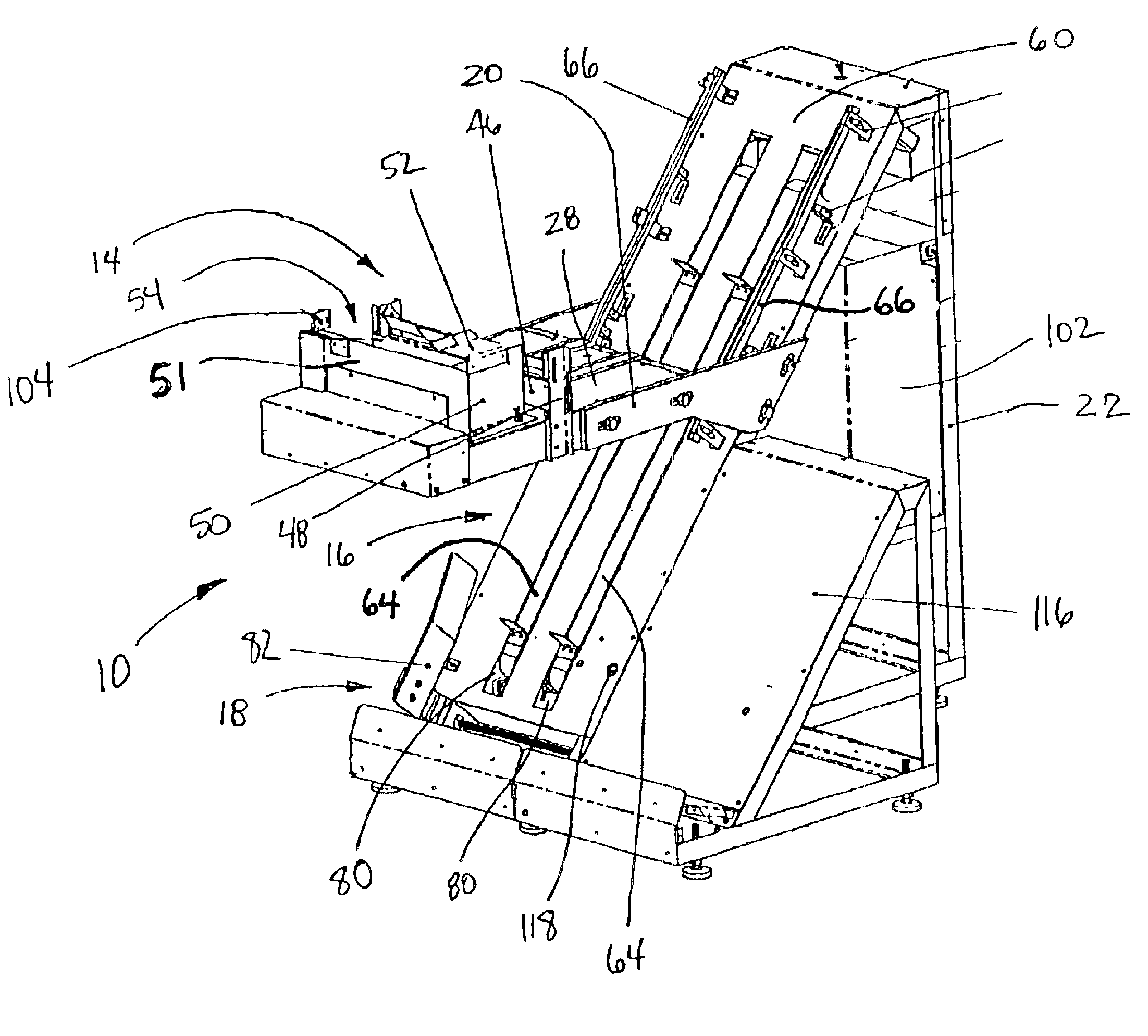
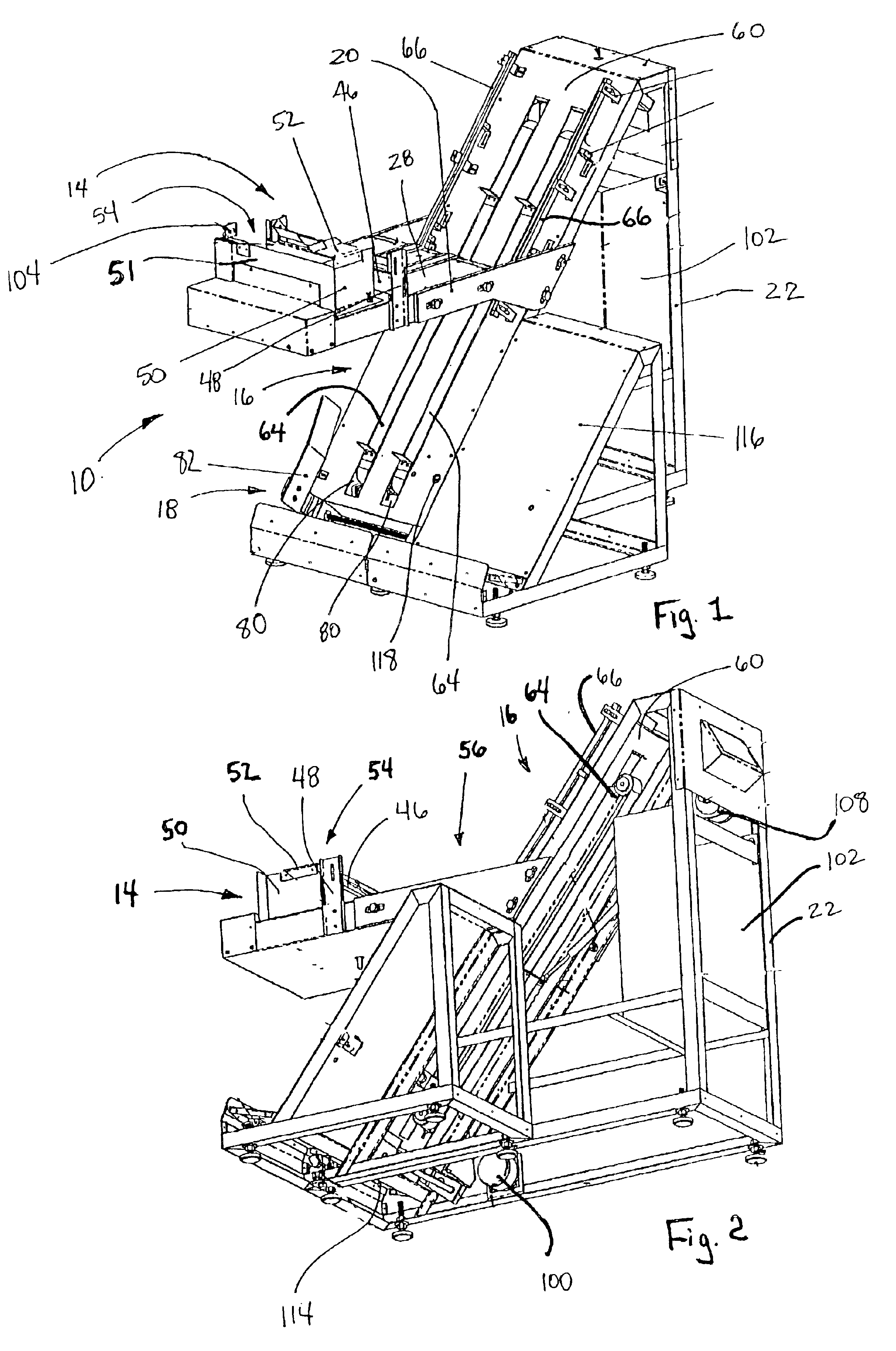
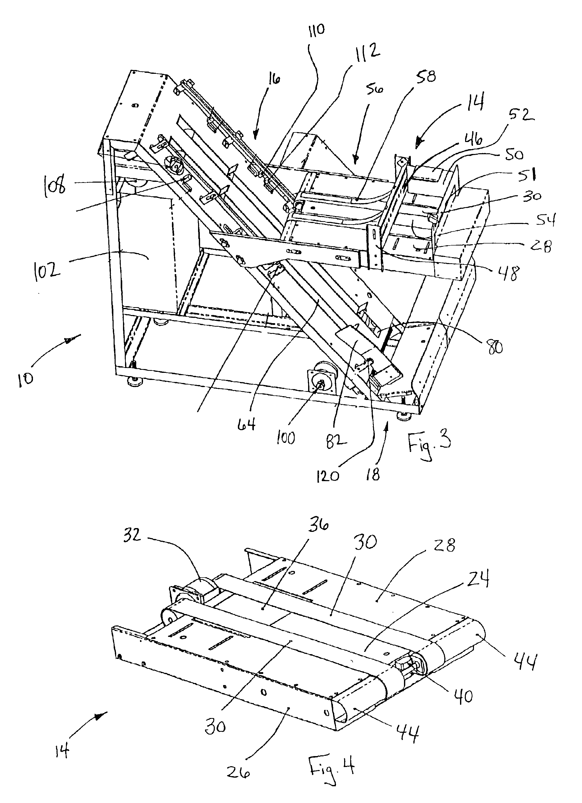
The embodiment shown in FIG. 1 is directed to a mail tray loading device 10 for association with mail inserter machines. Typically, the mail tray loading device 10 is positioned downstream from the mail inserter machine and either is connected to the mail inserter machine or positioned adjacent thereto.

The mail tray loading device 10, as shown in FIG. 1, comprises a two-stage envelope conveyor assembly 14, a tray conveyor...


PUM

PropertyMeasurementUnit
lengthaaaaaaaaaa
thicknessesaaaaaaaaaa
speedaaaaaaaaaa

Abstract

The invention is directed to an automatic mail tray loading device that is adapted to receive envelopes from an inserting machine or from other mail-processing systems and place them in mail trays. The device has a two-stage envelope buffer, which buffers the envelopes into a shingled array before depositing them into the mail tray. The first stage buffers the envelopes during purging of the second stage and the second stage buffers the mail during a tray change. The mail trays are held on a tray conveyor, at an inclination that ensures proper loading of the tray and reliable transfer of envelopes from the tray. The tray conveyor incrementally moves the envelope tray downward until the tray is full of envelopes. A new, empty tray is then moved into position and the filled tray is moved laterally to the tray offload station. The system comprises an envelope conveyor, a tray conveyor, a lateral tray transfer mechanism and an auxiliary buffer. The envelope conveyor receives the envelopes from the inserter and buffers them in a shingled stream before discharging them into the envelope tray. The tray conveyor positions the envelope tray to receive the envelopes as they are discharged from the envelope conveyor. The tray lateral transfer mechanism advances the filled tray laterally to the offload station. The auxiliary buffer is located at the upstream end of the envelope conveyor and functions as the auxiliary buffer to buffer envelopes arriving from the inserter during purging of the envelope conveyor prior to a tray change.

Description

BACKGROUND OF THE INVENTIONThe present invention relates to mail tray loading devices used for automatically loading mail into mail trays. The mail tray loader is designed to eliminate the need for manual intervention during the tray loading process. The mail tray loader is also designed to reduce the cost and complexity found in present tray loading machinery. In a typical inserting machine installation, the envelopes exiting the inserting machine (inserter) are transferred from the inserter onto a low-speed conveyor on which the envelopes accumulate in a shingled stream. Transfer of mail from this conveyor to the mail tray is usually accomplished manually. This tends to stifle productivity, particularly in high-volume operations. Although some automatic traying machines exist, they are relatively complicated and expensive. The present invention replaces the traditional output conveyor and offers a compact and cost-effective means for loading the mail into trays automatically.SUMMA...

Claims


Application Information

Patent Timeline
Patent Type & Authority Patents(United States)
IPC IPC(8): B65H29/16B65H29/18B65H31/30B65H3/04B65H3/02
CPCB65H29/18B65H29/669B65H31/3081B65H83/02B65H2701/1916B65H2301/4213B65H2301/422548B65H2301/42322
Inventor RABINDRAN, K. GEORGE
Owner RABINDRAN K GEORGE
Features
  • R&D
  • Intellectual Property
  • Life Sciences
  • Materials
  • Tech Scout
  • Unparalleled Data Quality
  • Higher Quality Content
  • 60% Fewer Hallucinations
Learn More