
Connector for glow sticks having display area

a technology of connecting wires and glow sticks, which is applied in the field of connecting wires, can solve the problems of limiting the size and shape of advertisements, little space available on the connector, and not allowing for the convenient display of advertisements, and achieves the effects of preventing the breakage of the connector, low cost, and low density

Inactive Publication Date: 2005-01-11
THE GLOW STORE
View PDF8 Cites 15 Cited by
  • Summary
  • Abstract
  • Description
  • Claims
  • Application Information

AI Technical Summary

Benefits of technology

The connector is made to receive the ends of a chemiluminescent light stick to create a necklace, bracelet, anklet or other circular object. The connector is preferably made of flexible, low cost, low density, polyethylene. There is preferably a partial separation at the centre of the connector under the display area which allows the connector to bend at such centre, allowing the bracelet, necklace or anklet to properly maintain its circular shape and to prevent the connector from breaking.
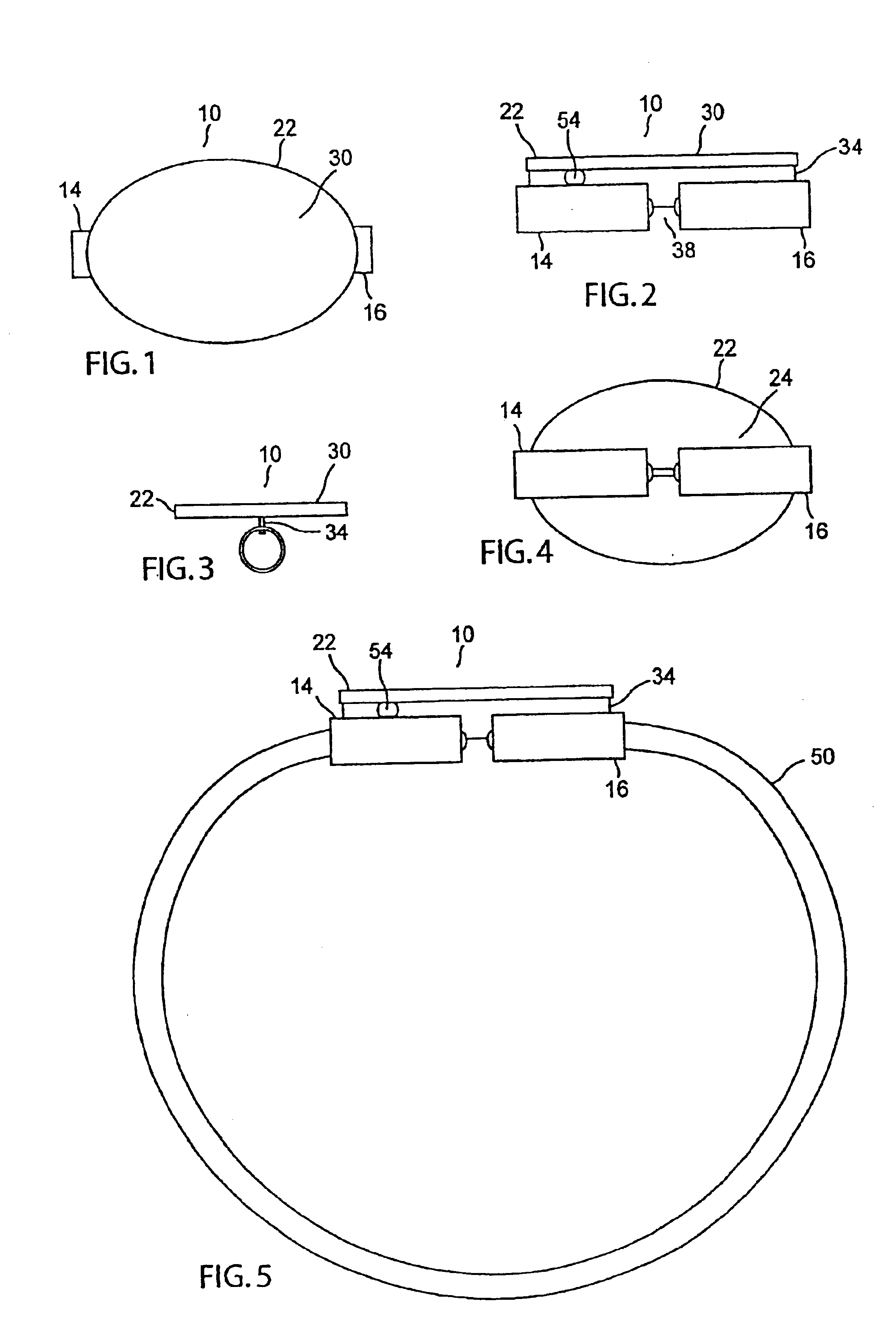
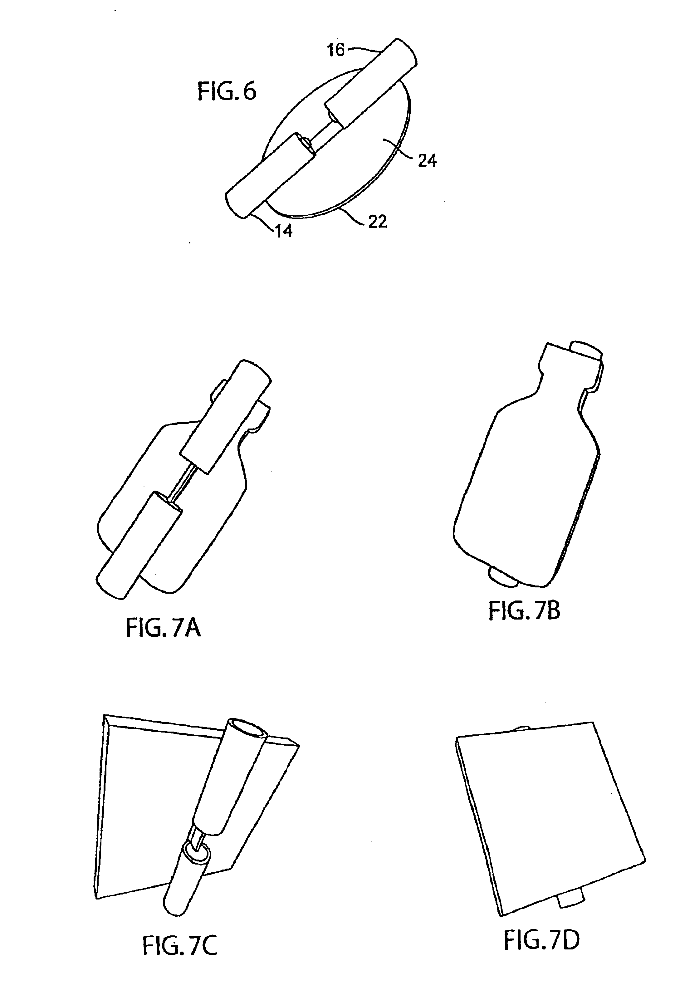
Another function of this connector is as a marketing tool. The display area is a preferably flat area on the connector which can be imprinted with virtually any likeness or corporate logo. The display area is preferably not a separate piece of the connector, so that the connector can be manufactured as a single piece. The display area is preferably slightly raised above the actual connector portion on a thin ridge running along the display area. The ridge helps to provide flexibility and also allows the connector to be mounted in a jig for hot stamping or pad printing of the display area. The mold for the connector is preferably designed to allow the display area to be manufactured in virtually any shape desired (i.e. oval, circle, square, bottle shape, letter(s), number(s), etc.) by incorporating an inexpensive interchangeable portion in the mold. This design addition allows the shape of the display area to be changed when needed at minimal cost.

Problems solved by technology

However, the connector does not allow for the convenient display of advertising.
As connectors known in the art are sized to closely match the diameter and shape of the tubular glow stick, there is little space available on the connector for advertising, which limits the size and shape of the advertisement.
Another problem associated with imprinting advertisements on the glow stick directly is that when a hot stamp or pad print method is used on the glow stick, approximately 1-2% of the glow sticks will break on such imprinting.

Method used


Image

  • Connector for glow sticks having display area
  • Connector for glow sticks having display area
  • Connector for glow sticks having display area

Examples


Embodiment Construction

For the purposes of this specification and appended claims (but not for the purposes of describing the prior art), the term “display area” means a portion of the connector described herein that is suited for displaying information on the exterior of the glow stick or engaging member, i.e. the information is not within the glow stick or engaging member. The display area includes, but is not limited to a flat surface branded with a logo, letters and / or numbers; a flat logo, numbering or lettering; a aesthetically pleasing design; or a three dimensional shape, such as a figure or decorative pendant.

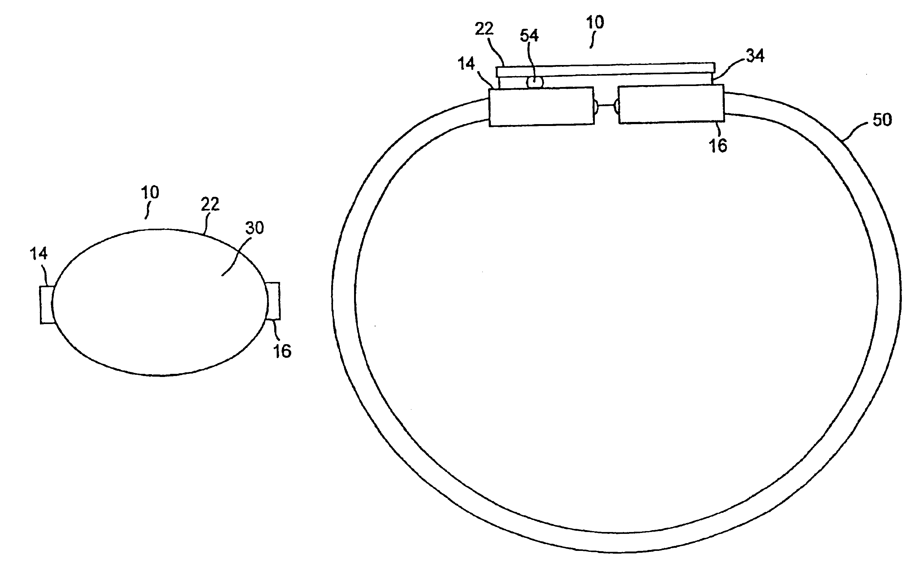
As seen in FIG. 1, a glow stick connector 10 according to the invention comprises first and second engaging members 14, 16, respectively for engaging opposite ends of a glow stick 50. First and second engaging members 14, 16 are generally cylindrically shaped and are sized to secure a glow stick by a tension fit. To perform this function first and second engaging members 14, 16 are usually f...


PUM


Abstract

A connector for glow sticks having first and second engaging members for engaging first and second ends of a glow stick. Positioned above the engaging members is a display area for the display of advertising or other information. The engaging members are typically shaped to fit the generally cylindrical glow stick. The ends of the glow stick are inserted into the engaging members, allowing the glow stick to function as a necklace or bracelet while displaying advertising, for example the logo of the sponsor of an event the user is attending.

Description

NOTICE REGARDING COPYRIGHTED MATERIALA portion of the disclosure of this patent document contains material which is subject to copyright protection. The copyright owner has no objection to the facsimile reproduction by anyone of the patent document or the patent disclosure as it appears in the public Patent Office file or records but otherwise reserves all copyright rights whatsoever.TECHNICAL FIELDThis invention relates generally to connectors for application with chemiluminescent glow sticks and particularly to such connectors that allow such glow sticks to be worn as jewellery.BACKGROUNDThe use of chemiluminescent glow sticks is seen commonly at entertainment events, such as concerts and sporting events. The glow sticks are frequently fashioned as flexible plastic tubes containing the chemiluminescent material, and it is often desirable that these tubes be maintained in a circular position to function as necklaces or bracelets. In order to maintain the glow sticks in such a shape...

Claims


Application Information

Patent Timeline
IPC IPC(8): F21K2/00F21K2/06G09F13/20G09F21/00G09F21/02A44C15/00
CPCA44C15/0015F21K2/06G09F21/02G09F13/20Y10T24/45958Y10T24/45984
Inventor BRYANT, ROBERTDOMBOWSKY, GREG
Owner THE GLOW STORE
Learn More