
Resin infusion mold tool system and vacuum assisted resin transfer molding with subsequent pressure bleed

a technology of resin infusion mold and vacuum assisted resin, which is applied in the direction of dough shaping, manufacturing tools, applications, etc., can solve the problems of affecting the dimensional tolerance of the resulting composite structure, affecting the and many vartm structures, however, fail to meet the more stringent structural criteria required for primary structures. , to achieve the effect of significant cost and labor savings and high fiber volume fraction

Inactive Publication Date: 2005-01-11
THE BOEING CO
View PDF27 Cites 62 Cited by
  • Summary
  • Abstract
  • Description
  • Claims
  • Application Information

AI Technical Summary

Benefits of technology

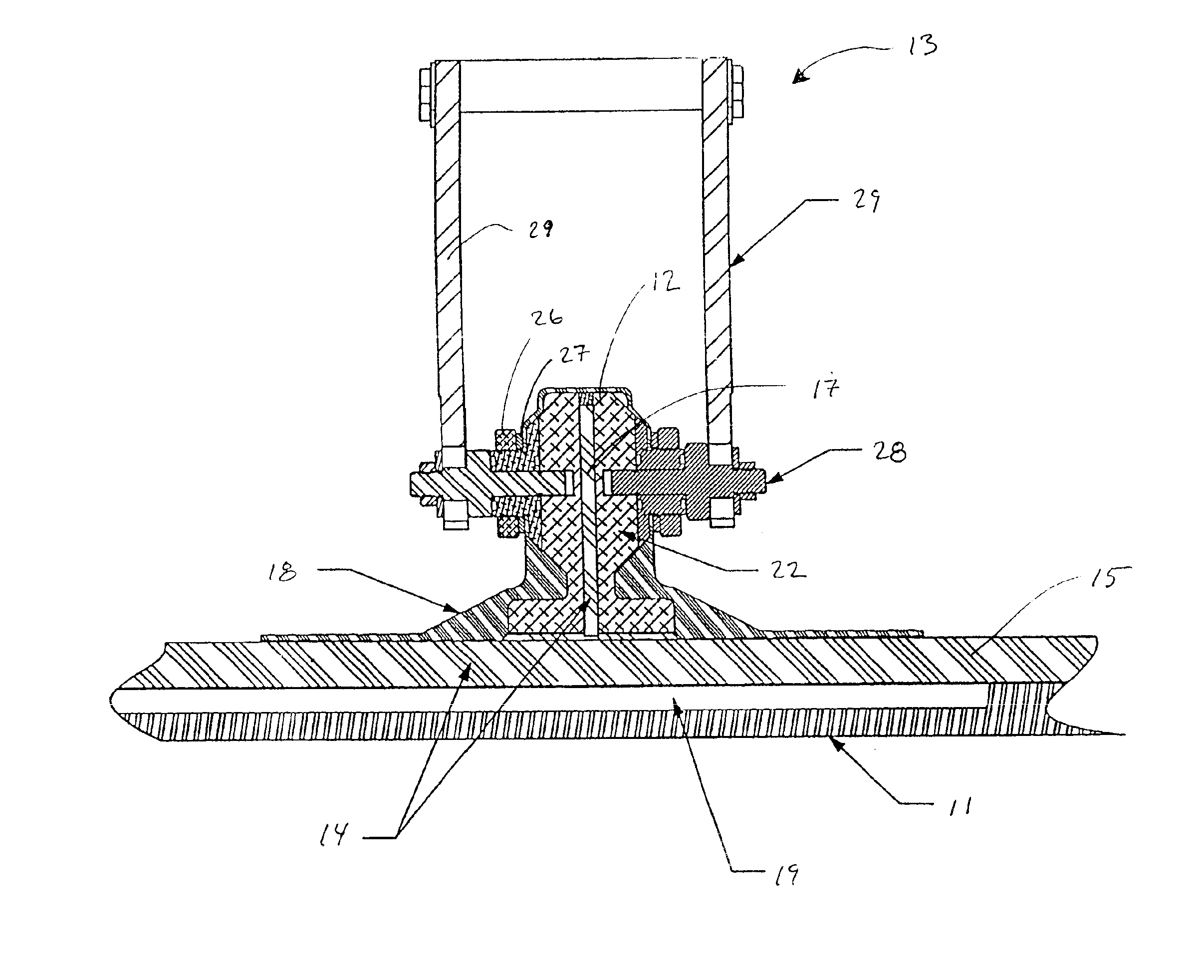
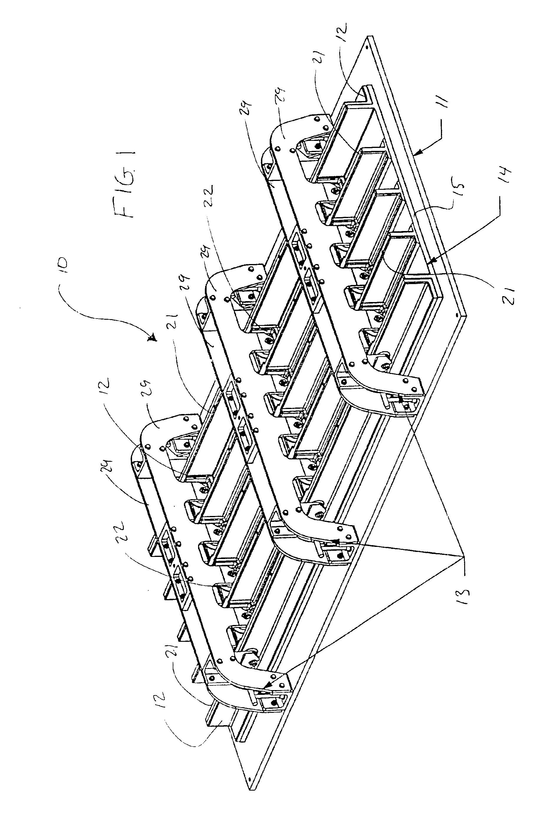
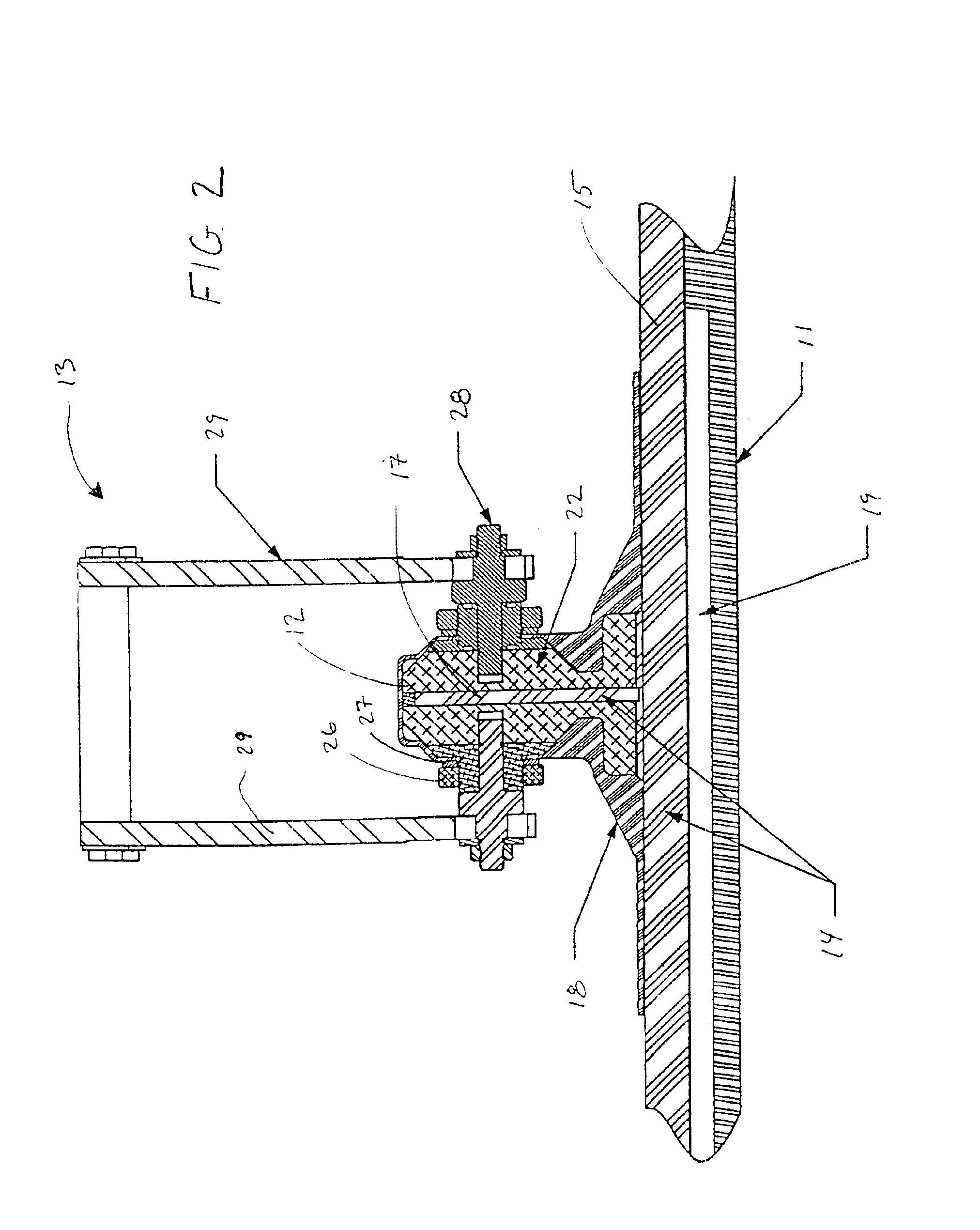
The present invention provides a resin infusion mold tool system with vacuum assisted resin transfer molding that uses a subsequent pressure bleed to achieve high fiber volume fractions on complex composite structures. The system includes tooling with machined details that are positioned under a vacuum bag. The hard interface between the inner tooling and dry fiber perform allows for the formation of critical features within tight tolerances as the composite structure is being formed. The fiber volume fraction of the composite structure is increased from 54% to 57% or greater by the use of an additional bleed step in an autoclave. The mold tool system and pressure bleed method of the present invention has several advantages, such as large and complex fiber composite structures can be manufactured as a single piece, representing a significant cost and labor savings. The composite structure produced has a high fiber volume fraction allowing the large structures to be used in applications that experience large loads, such as airplane wings or marine structures. The hard tooling interface produces details and positions structural elements within relatively tight tolerances that are unavailable in conventional systems that use soft tooling.

Problems solved by technology

Each piece was produced individually and then assembled to create the larger structure in a labor-intensive and costly process.
Large displacements of the mold tooling and the fiber perform can adversely affect the dimensional tolerances of the resulting composite structure.
Many VARTM structures, however, fail to meet the more stringent structural criteria required for primary structures in aircraft.
Despite the improvement in structural complexity of the resulting composite part, the use of soft tooling limits the precision to which details can be produced on the part using the process of Biome et al.

Method used


Image

  • Resin infusion mold tool system and vacuum assisted resin transfer molding with subsequent pressure bleed
  • Resin infusion mold tool system and vacuum assisted resin transfer molding with subsequent pressure bleed
  • Resin infusion mold tool system and vacuum assisted resin transfer molding with subsequent pressure bleed

Examples


Embodiment Construction

The present invention now will be described more fully hereinafter with reference to the accompanying drawings, in which preferred embodiments of the invention are shown. This invention may, however, be embodied in many different forms and should not be construed as limited to the embodiments set forth herein; rather, these embodiments are provided so that this disclosure will be thorough and complete, and will fully convey the scope of the invention to those skilled in the art. Like numbers refer to like elements throughout.

The present invention allows for the construction of large fiber composite structures with inner mold lines having tight tolerances and intricate detailing by using hard tooling. In addition, the present invention uses a post bleed step in an autoclave to increase the fiber volume of the completed composite structure, lending the structure sufficient strength for use in the primary structures of aircraft, marine applications and the like.

FIG. 1 depicts a perspec...


PUM

PropertyMeasurementUnit
pressuresaaaaaaaaaa
lengthaaaaaaaaaa
volume fractionaaaaaaaaaa

Abstract

A resin infusion mold tool system for use in a vacuum assisted resin transfer molding process with a subsequent pressure bleed step. The mold tool system includes a mold assembly having an outer mold line tool connected to resin supply lines and supplying resin to the preform. A plurality of inner mold line tools form a hard interface with the inner mold line of the fiber preform and are held to within tight tolerances by an external locating fixture. Excess resin is drawn out of the fiber preform using a vacuum bag connected to vacuum lines and disposed over the inner mold line tools but not between the tools and the fiber preform. The mold assembly is placed in an autoclave, the resin supply lines are detached and the autoclave pressurized to bleed additional resin out of the preform to raise the fiber volume of the composite structure.

Description

FIELD OF THE INVENTIONThe present invention relates to the fabrication of composite structures, in particular the fabrication of composite structures using a tool assembly to support a dry fiber preform and vacuum assisted resin transfer molding to infuse resin into the dry fiber preform.BACKGROUND OF THE INVENTIONThe production of large and complex fiber composite structures, such as airplane wings, requires critically dimensioned features to be held within narrow tolerances. Until recently, process for the production of large and complex fiber composite structures did not exist. Large and complex structures had to be broken down into multiple pieces of a more simple design. Each piece was produced individually and then assembled to create the larger structure in a labor-intensive and costly process.The development of resin film infusion (RFI) methods and the mold tooling used with RFI methods, as demonstrated in U.S. Pat. No. 5,902,535 to Burgess et al., has allowed the production...

Claims


Application Information

Patent Timeline
Patent Type & Authority Patents(United States)
IPC IPC(8): B29C70/04B29C70/44B29C70/48B29C70/54
CPCB29C70/443B29C70/548B29C70/48
Inventor THRASH, PATRICK J.BURGESS, ROGER ALANMARKUS, ALAN M.
Owner THE BOEING CO
Learn More