
Electrosurgical ablator with aspiration

a technology of ablator and ablator plate, which is applied in the field of electrosurgical devices, can solve the problems of low cost, complex metal shape, and precise production of metal shapes from metallic materials, and achieve the effects of low cost, low cost, and precise metal shape production

Inactive Publication Date: 2005-01-11
ELECTROSURGERY ASSOCS
View PDF12 Cites 56 Cited by
  • Summary
  • Abstract
  • Description
  • Claims
  • Application Information

AI Technical Summary

Benefits of technology

The present invention provides an aspirating ablator of simple construction having a proximal portion forming a handle and an elongated tubular distal portion, the distal tip of which is formed to an ablating surface.
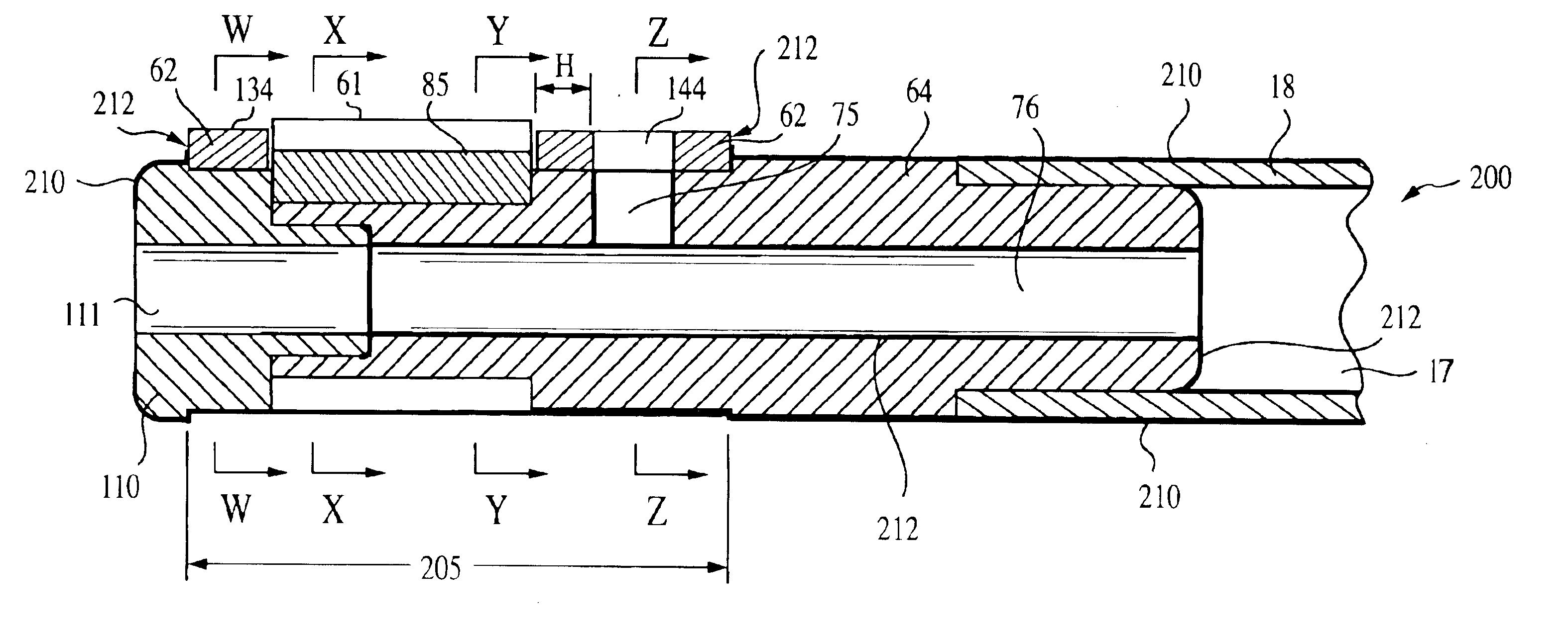
The elongated tubular member of the aspirating ablator electrode of the present invention comprises a stainless steel tube provided at its proximal end with an alignment / connector piece, which provides angular alignment of the tube relative to the handle. At its distal end, the tube is provided with a mandrel connected to the tube. The mandrel has a tubular shape, having an inner lumen and a cylindrical external shape. A cylindrical passage extends from the inner lumen radially upward to the upper surface of the mandrel a short distance distal from the end of the stainless tube. An electrode piece of stainless steel, titanium or other metallic material has a tubular section with an inner diameter suitable for assembly onto the mandrel and a rectangular ablation surface formed of multiple parallel ribs or protuberances separated by grooves. The electrode piece is assembled onto the mandrel so that the ablation surface is parallel with the upper surface of the handle, and the intersection of the radial passage with the mandrel upper surface is positioned proximally for less than about 1 centimeter from the proximal end of said ablation surface. A ceramic or polymeric tip cap is attached at the end of the mandrel, the tip cap having a cylindrical passage which is coaxial with the lumen in the mandrel, thereby providing a means for suction supplied to the tubular member to aspirate materials in the proximity to the distal-most face of the tip cap. The inner lumen of the tubular member and mandrel and mandrel radial passage are covered with an insulating material so as to prevent contact between fluid and metallic surfaces.
In another embodiment, the electrode is integral with the mandrel. In this embodiment the entire electrode / mandrel component is preferably made from the desired electrode material. The component may be made either by turning on a Swiss-style screw machine followed by secondary machining of grooves in the electrode surface, or by metal injection molding. Although the latter process requires machining of an injection mold, it is able to produce precise, complex, metal shapes from metallic materials at very low costs.
In another embodiment, the electrode is integral with the mandrel as in the previous embodiment, however, the ribs or protuberances of the active electrode are circumferential rather than axial, and lateral-facing surfaces of the electrode are angled to be tangential to the component's cylindrical section. This configuration allows the assembled component to be made complete on a Swiss-style screw machine with no secondary operations required, thereby lowering the manufacturing cost. Alternatively, metal injection molding may be used to produce the component. An advantage of this embodiment is that, during production scale-up, the component may be manufactured at low cost by machining until sales volumes are sufficient to justify the cost of an injection mold to achieve further cost savings.

Problems solved by technology

Although the latter process requires machining of an injection mold, it is able to produce precise, complex, metal shapes from metallic materials at very low costs.

Method used


Image

  • Electrosurgical ablator with aspiration
  • Electrosurgical ablator with aspiration
  • Electrosurgical ablator with aspiration

Examples


Embodiment Construction

In the following detailed description, reference is made to the accompanying drawings which form a part hereof, and in which is shown by way of illustration specific embodiments in which the invention may be practiced. These embodiments are described in sufficient detail to enable those skilled in the art to practice the invention, and it is to be understood that other embodiments may be utilized, and that structural, logical and electrical changes may be made without departing from the spirit and scope of the present invention.

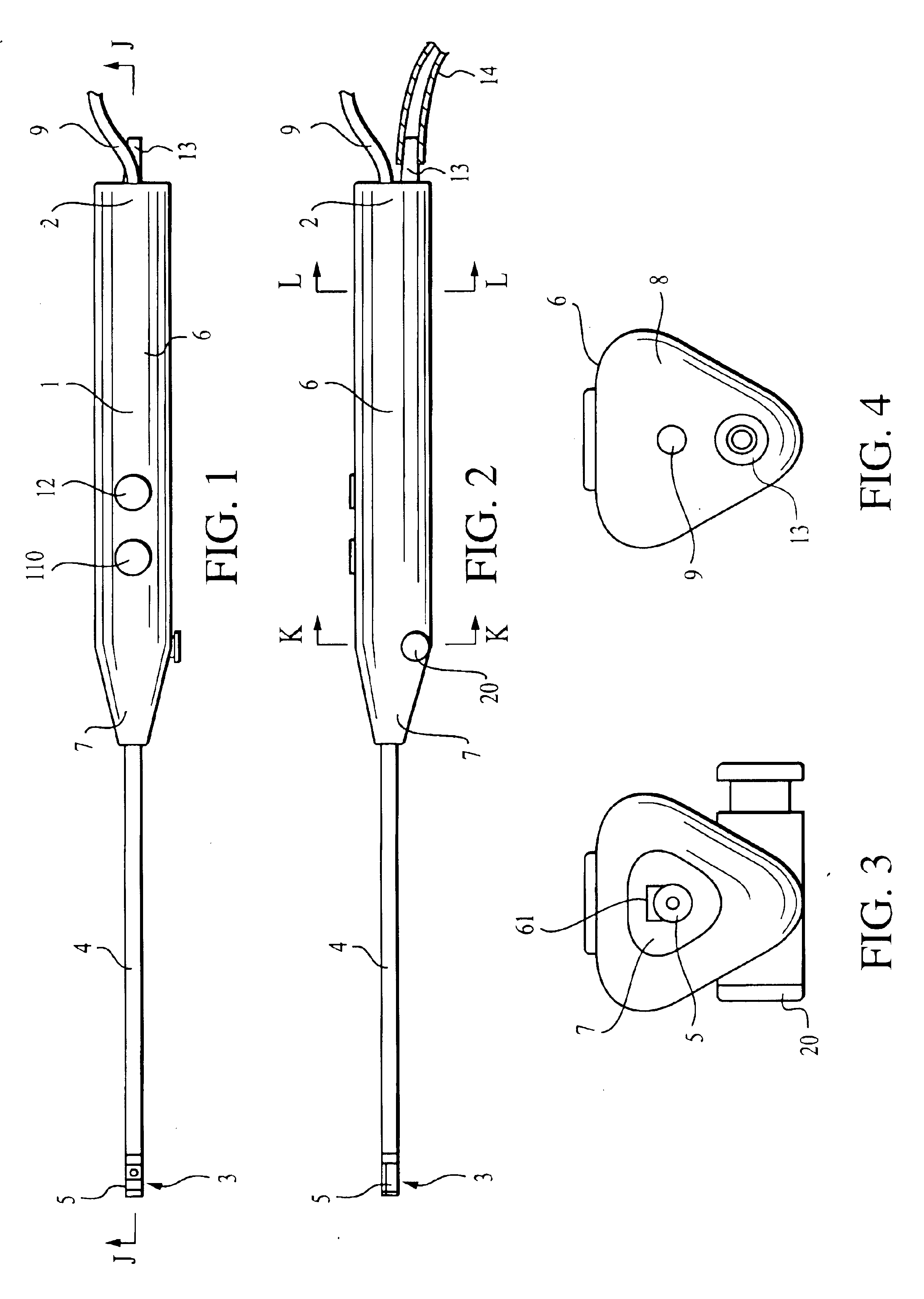
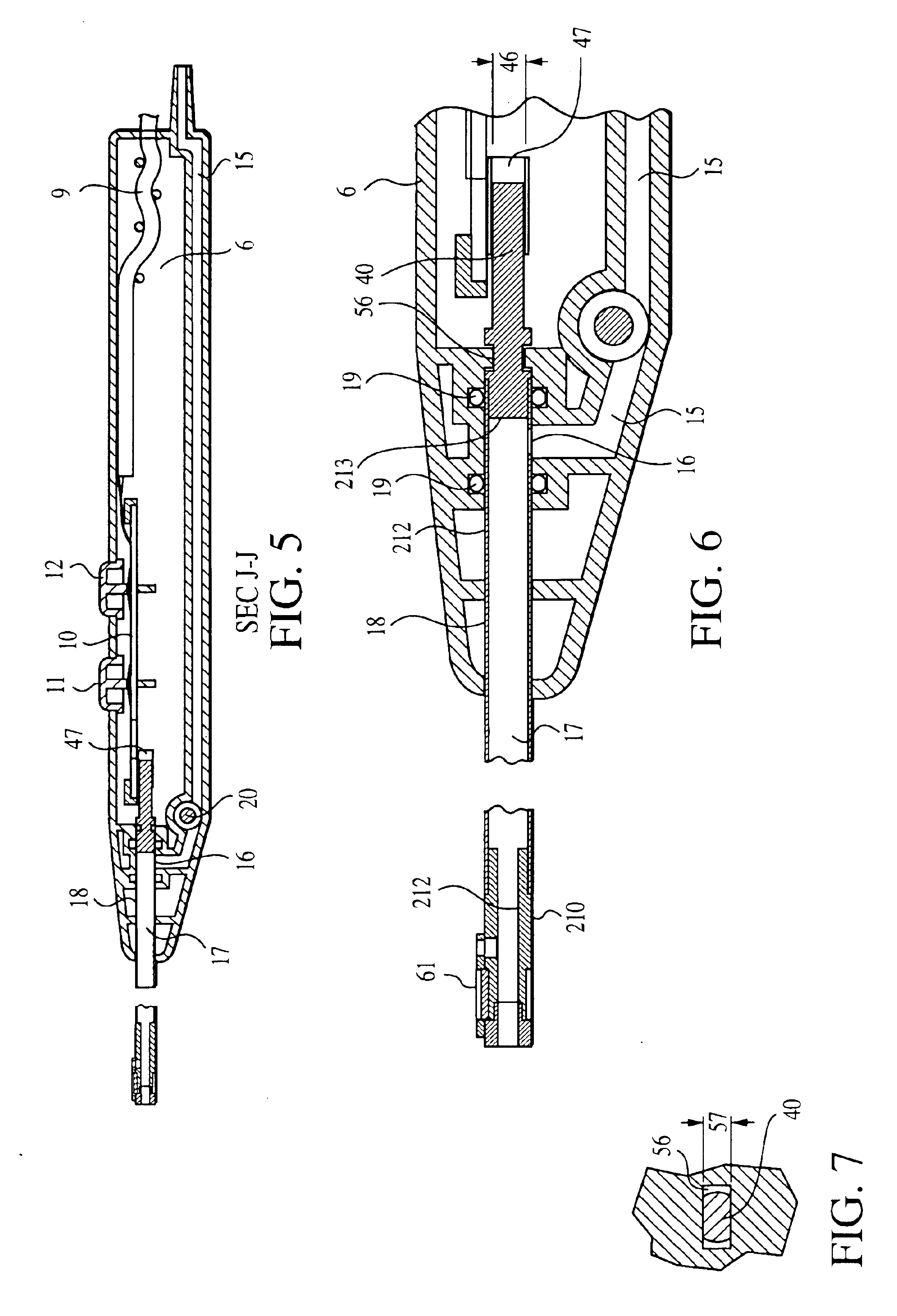
Referring now to the drawings, where like elements are designated by like reference numerals, FIGS. 1 and 2 illustrate an aspirating ablator 1 constructed in accordance with the present invention and having a proximal end 2, a distal end 3, an elongated distal portion 4 terminating in an electrode assembly 5 suitable for arthroscopic ablation of tissue, and a proximal portion 6 that forms a handle. The handle 6 has a proximal end 2 and a distal end 7 (also sh...


PUM


Abstract

An aspirating ablator of simple construction and low cost is disclosed. The aspirating ablator is provided with a mandrel connected to a tubular member which houses a suction assembly. An electrode having a rectangular ablation surface formed of multiple parallel ribs or protuberances is assembled onto the mandrel so that the ablation surface is parallel with the longitudinal axis of the mandrel. A ceramic insulator provided with an opening of rectangular shape is assembled to the electrode-mandrel assembly. The insulator is further provided with a cylindrical passage in communication and aligned with a radial passage of the mandrel.

Description

FIELD OF THE INVENTIONThe present invention relates to the field of electrosurgery and, in particular, to electrosurgical devices and methods which employ high frequency voltage to cut, ablate or coagulate tissue in a conductive fluid environment.BACKGROUND OF THE INVENTIONLeast invasive surgical techniques have gained significant popularity because of their ability to accomplish outcomes with reduced patient pain and accelerated return of the patient to normal activities. Arthroscopic surgery, in which the intra-articular space is filled with fluid, allows orthopedic surgeons to efficiently perform procedures using special purpose instruments designed specifically for arthroscopists. Among these special purpose tools are various manual graspers and biters, powered shaver blades and burs, and electrosurgical devices. During the last several years specialized arthroscopic electrosurgical electrodes called ablators have been developed. Exemplary of these instruments are ArthroWands ma...

Claims


Application Information

Patent Timeline
IPC IPC(8): A61B18/14
CPCA61B18/1402A61B2018/00577A61B2218/007A61B2018/00601A61B2018/1467A61B2018/00589
Inventor VAN WYK, ROBERT A.
Owner ELECTROSURGERY ASSOCS
Learn More