
Guideless stage with isolated reaction stage

a reaction stage and guideless technology, applied in the field of electromechanical alignment and isolation, can solve the problems of unwanted vibration, many parts, and high precision of structures, and achieve the effect of minimizing vibration coupled and minimizing vibration coupled

Inactive Publication Date: 2005-01-11
NIKON CORP
View PDF124 Cites 135 Cited by
  • Summary
  • Abstract
  • Description
  • Claims
  • Application Information

AI Technical Summary

Benefits of technology

A feature, an advantage of this invention is the provision of a support, positioning and isolation assembly which allows the positioning function of the object or wafer stage to be accomplished while minimizing vibrations coupled to the stage and lens systems from the reaction stage faster and with fewer parts while minimizing vibrations coupled to the stage and isolating the stage from undesired reaction forces.

Problems solved by technology

These structures require high precision and many parts.
Typically, external forces directed to parts of the positioning assembly and reaction forces due to movement of different parts of the assembly are coupled directly to the image forming optics and reticle handling equipment resulting in unwanted vibration.

Method used


Image

  • Guideless stage with isolated reaction stage
  • Guideless stage with isolated reaction stage
  • Guideless stage with isolated reaction stage

Examples


Embodiment Construction

While it will be appreciated by those skilled in the art that the guideless stage, with or without its isolating reaction frame, has many applications to many different types of instruments for precise positioning of objects, the present invention will be described with respect to a preferred embodiment in the form of a microlitholigraphic instrument for aligning wafers in a system where a lens produces an image which is exposed to the photoresist on the wafer surface. In addition, while the guideless stage with or without its isolation stage can be utilized as a guideless object stage movable in just one direction, such as a X or a Y direction, the preferred embodiment is directed to a guideless XY wafer stage as described below.

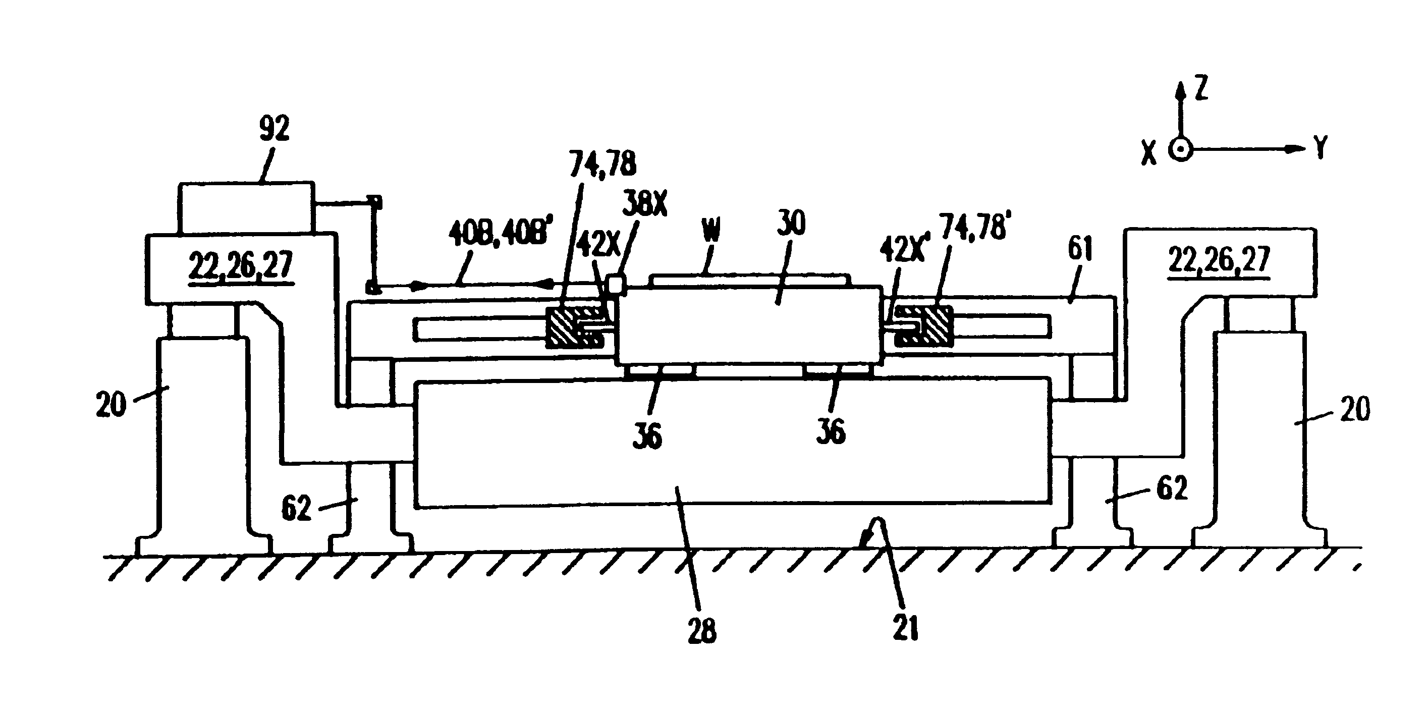
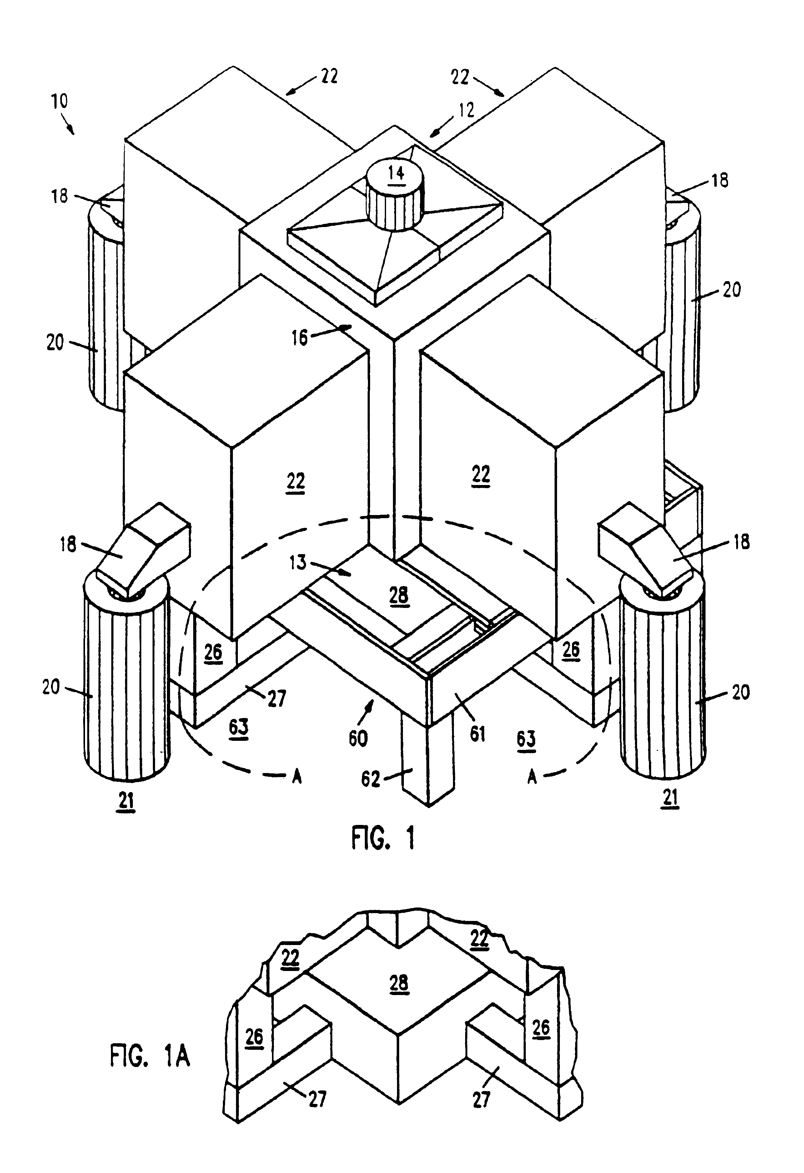
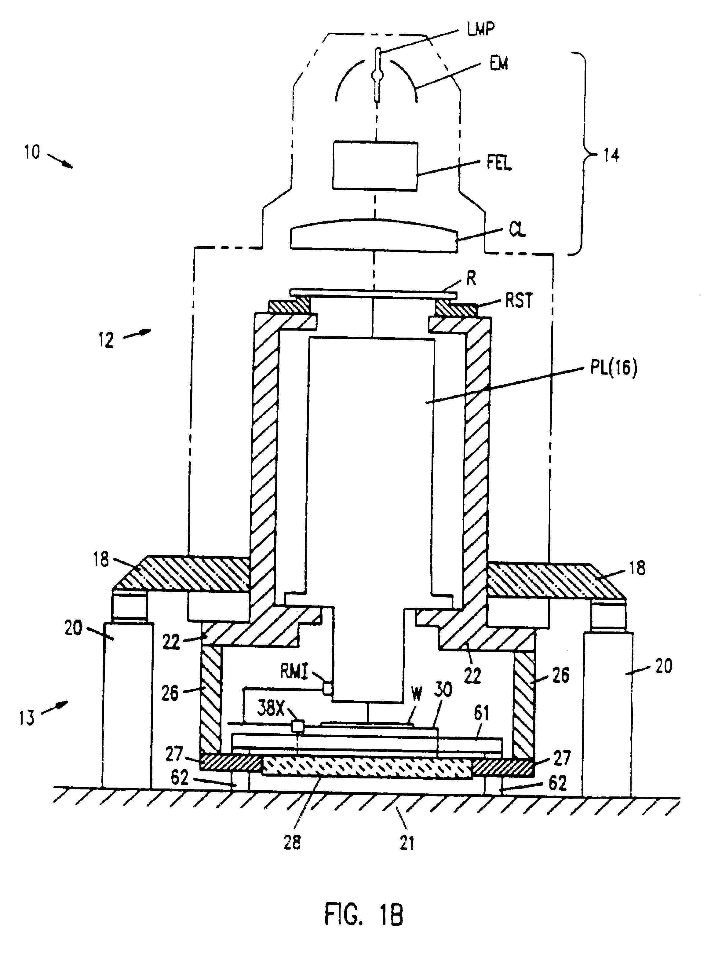
Referring now to the drawings, with particular reference to FIGS. 1 and 2, there is shown a photolithographic instrument 10 having an upper optical system 12 and a lower wafer support and positioning system 13. The optical system 12 includes an illuminator ...


PUM


Abstract

A guideless stage for aligning a wafer in a microlithography system is disclosed, and a reaction frame is disclosed which isolates both external vibrations as well as vibrations caused by reaction forces from an object stage. In the guideless stage an object stage is disclosed for movement in at least two directions and two separate and independently movable followers move and follow the object stage and cooperating linear force actuators are mounted on the object stage and the followers for positioning the object stage in the first and second directions. The reaction frame is mounted on a base structure independent of the base for the object stage so that the object stage is supported in space independent of the reaction frame. At least one follower is disclosed having a pair of arms which are respectively movable in a pair of parallel planes with the center of gravity of the object stage therebetween. The linear positioning forces of the actuator drive means are mounted and controlled so that the vector sum of the moments of force at the center of gravity of the object stage due to the positioning forces of the drive means is substantially equal to zero. The actuator mounting means can include at least two thin flexible members mounted in series with the primary direction of flex of the members being orthogonal to one another.

Description

FIELD OF THE INVENTIONThe present invention relates, in general, to electro-mechanical alignment and isolation and, more particularly, to such method and apparatus for supporting and aligning a wafer in a microlithographic system and isolating the system from its own reaction forces and external vibrations.BACKGROUND OF THE INVENTIONVarious support and positioning structures are known for use in microlithographic instruments. Typically, in the prior art, XY guides, including a separate X guide assembly and Y guide assembly, are utilized with one guide assembly mounted on and movable with the other guide assembly. Often, a separate wafer stage is mounted on top of these guide assemblies. These structures require high precision and many parts. Typically, external forces directed to parts of the positioning assembly and reaction forces due to movement of different parts of the assembly are coupled directly to the image forming optics and reticle handling equipment resulting in unwanted...

Claims


Application Information

Patent Timeline
IPC IPC(8): G03F7/20H01L21/68H01L21/67F16F15/02G12B5/00G03F7/24G03F9/00H01L21/027H01L21/30
CPCG03F7/70716G03F7/709H01L21/682H01L21/68Y10T74/20207H01L21/30
Inventor LEE, MARTIN E.
Owner NIKON CORP
Learn More