Nuclear magnetic resonance apparatus and methods for analyzing fluids extracted from earth formation

a technology of nuclear magnetic resonance and extraction fluid, which is applied in the field of methods for analyzing extracted formation fluid, can solve the problems of reversible changes, many inefficiencies inherent in this process, and the oil producing formation is almost always undersampled

Inactive Publication Date: 2005-01-11
SCHLUMBERGER TECH CORP
View PDF29 Cites 36 Cited by
  • Summary
  • Abstract
  • Description
  • Claims
  • Application Information

AI Technical Summary

Benefits of technology

Alternatively, flow rate of a fluid may be determined by: a) flowing the fluid through a static magnetic field having a magnetic field gradient; b) applying a group of oscillating magnetic field pulses, each group of pulses comprising an initial pulse and one or more refocusing pulses; c) detecting magnetic resonance signals from the flowing fluid such that odd and even echoes are separately measured; d) analyzing the phase or amplitude of the odd and even echoes to determine the flow rate. One skilled in the art would recognize that the free induction decay following the initial pulse may be regarded as an “even echo” for this measurement; however, it is preferable to not use it in the measurement.
Because turbulence can affect some fluid flow rate measurements, it may be preferred to further monitor the onset of turbulence in the flowing fluid. The onset of turbulence may be monitored by comparing the amplitude of an earlier detected echo to one or more subsequent echoes, most preferably, the first echo is compared to later echoes.
The method of the present invention is particularly useful in downhole environments; however, it may also be practiced on samples in a laboratory setting.
Another embodiment of the present invention discloses an apparatus for analyzing a fluid in a downhole environment comprising: a) means for extracting the fluid from an earth formation into a flow channel within a well logging tool; b) means for generating a static magnetic field within the flow channel; c) means for generating one or more groups of oscillating magnetic field pulses to the fluid in the flow channel, wherein each group of pulses is comprised of an initial pulse followed by one or more refocusing pulses and wherein at least two of the groups of pulses are generated after a varied wait time; d) means for detecting magnetic resonance signals; and e) means for analyzing the detected magnetic resonance signals. Again, to eliminate any remnant magnetization, the group of magnetic field pulses may include an rf spoiler pulse.
Further details, features and embodiments of the invention will become more readily apparent from the detailed description that follows.

Problems solved by technology

There are many inefficiencies inherent in this process.
Thus, oil producing formations are almost always undersampled.
Reversible changes are deleterious because they occur slowly and therefore impact sample handling and measurement efficiency.
Further, the transportation and handling of fluids uphole entails all the dangers associated with the handling of volatile and flammable fluids at high pressure and temperature.
After analyses are complete, the samples must be disposed of in an environmentally acceptable manner, with associated financial and regulatory burdens.
In addition, because fluid analysis laboratories are frequently distant from the well site, there are substantial delays—often several weeks—in obtaining results.
If a sample is for some reason corrupted or lost during sampling, transporting, or measurement, there is little possibility of returning to the well to replace it.
No presently deployed system is generally useful for determining the characteristics of sampled formation fluids in-situ while flowing.

Method used


Image

  • Nuclear magnetic resonance apparatus and methods for analyzing fluids extracted from earth formation
  • Nuclear magnetic resonance apparatus and methods for analyzing fluids extracted from earth formation
  • Nuclear magnetic resonance apparatus and methods for analyzing fluids extracted from earth formation

Examples


Embodiment Construction

1. Variable Wait Time Measurement

Methodology

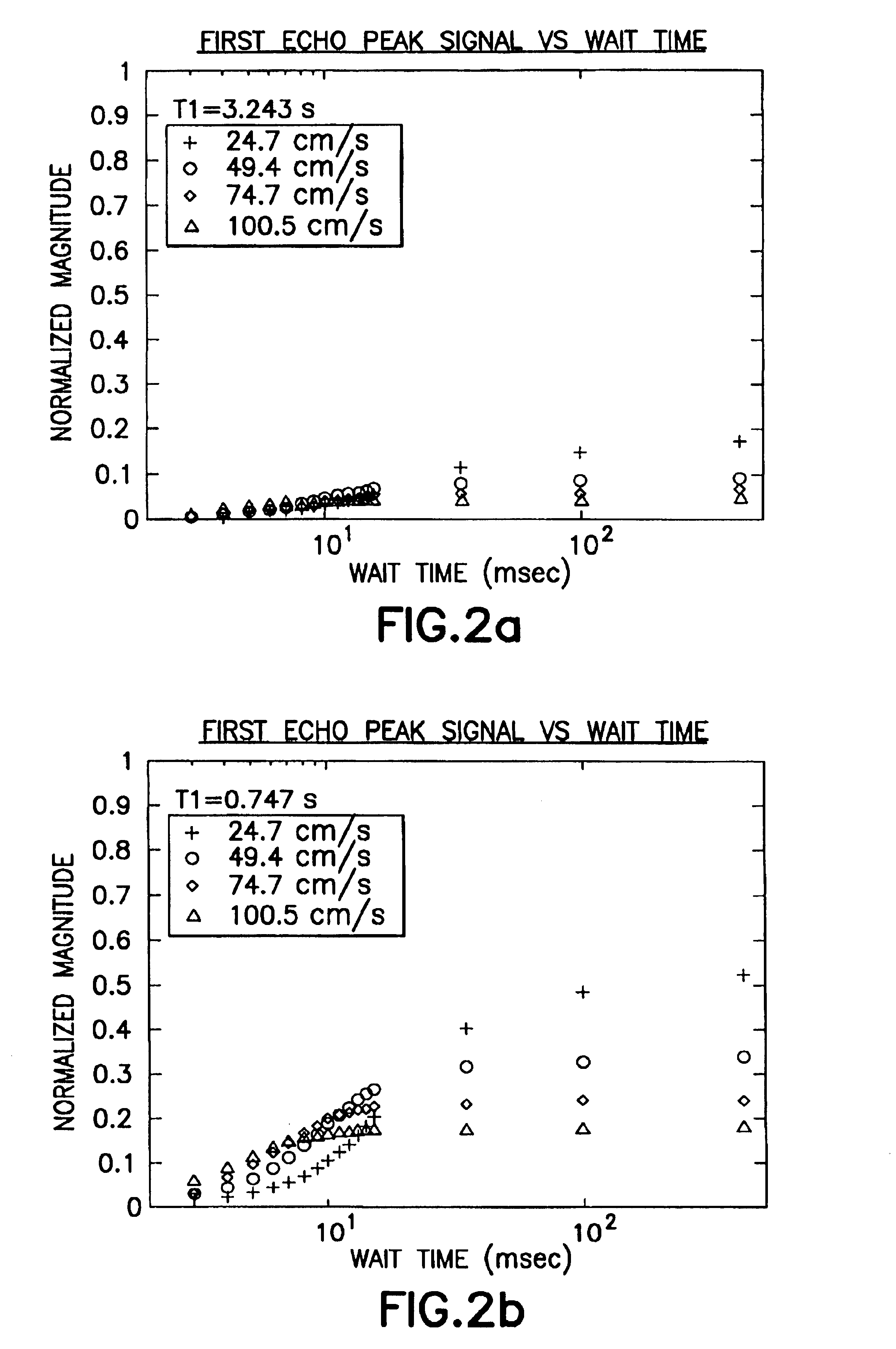
Variable wait time (VWT) measurements allow T1 measurements to be made on flowing samples. These measurements allow for fluid characterization (such as during pumpout) and flow rate calculations.

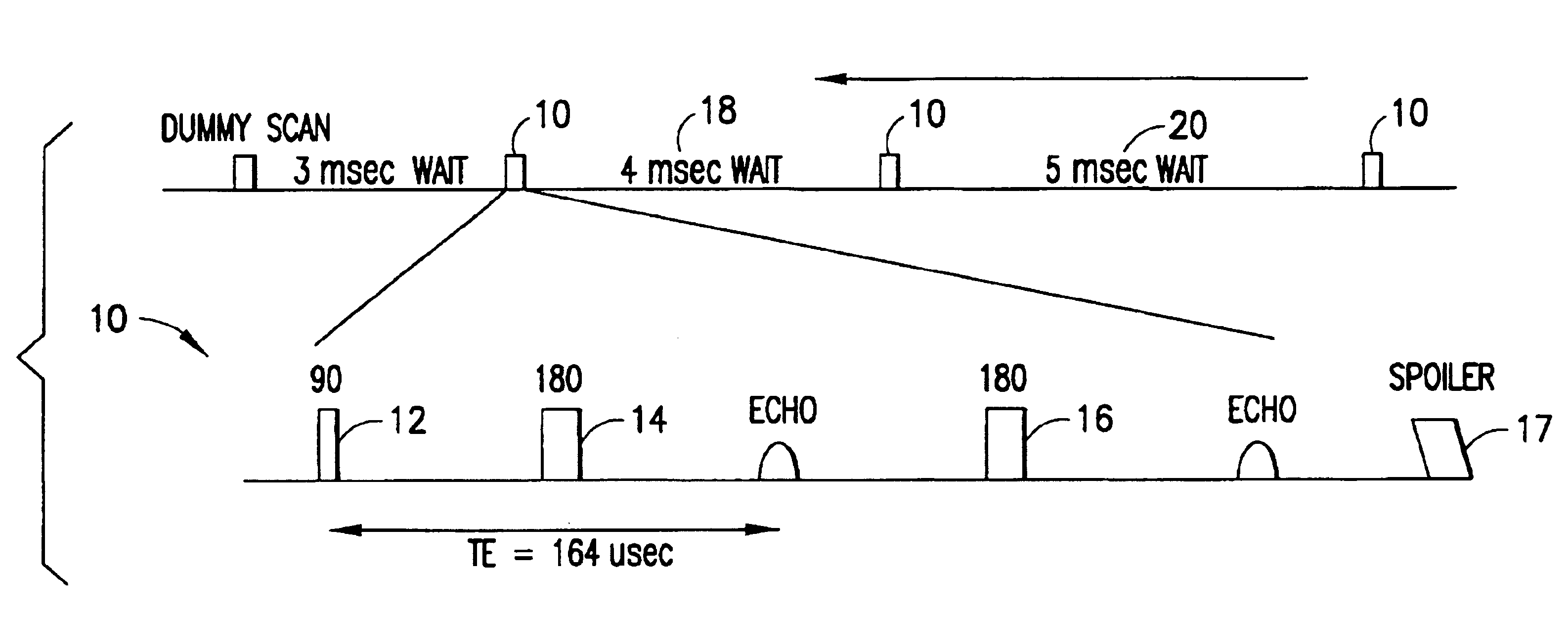
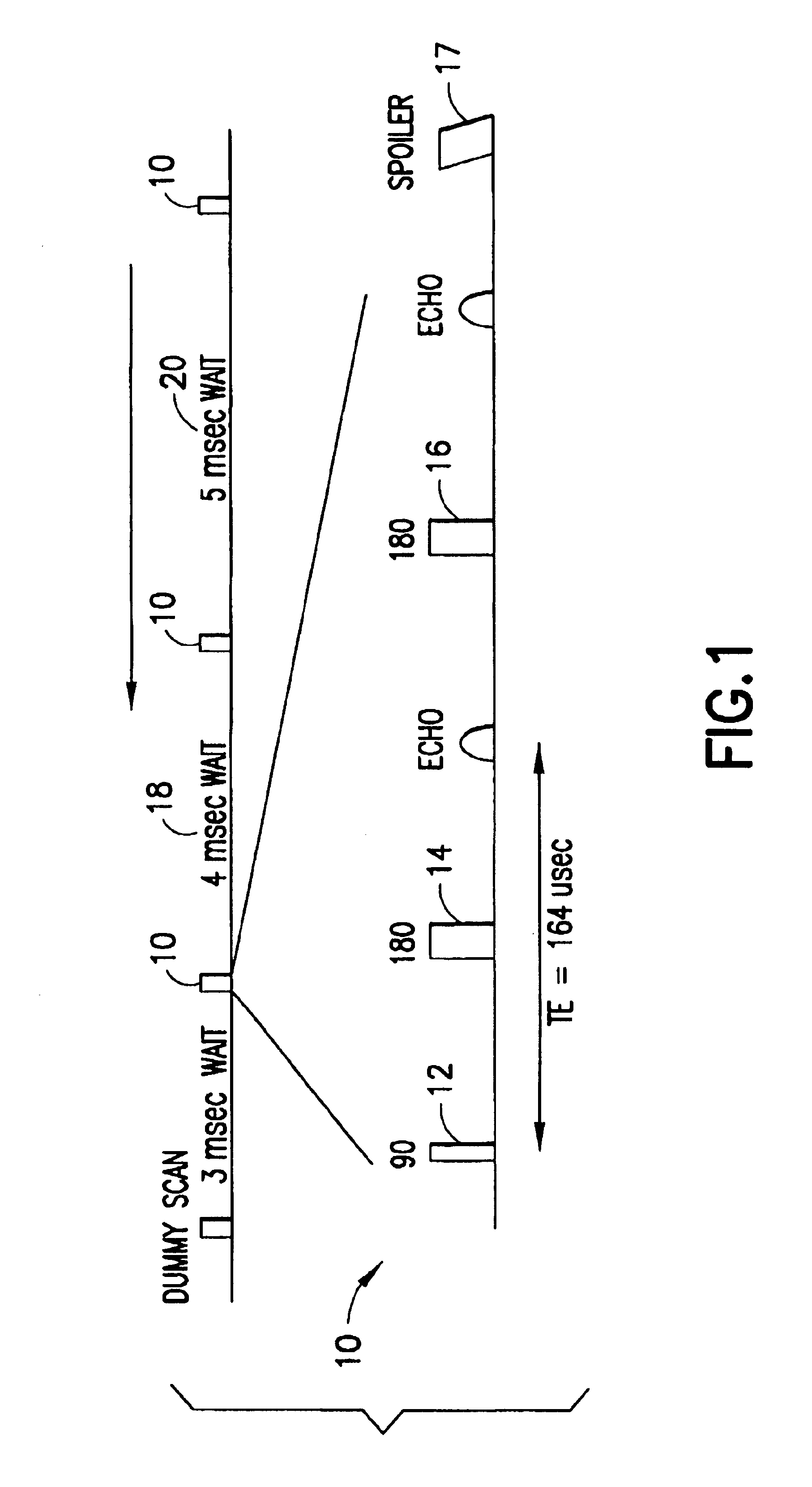
FIG. 1 shows a non-limiting pulse sequence useful in the present invention. In this example, each group of pulses 10 is comprised of an initial pulse 12 and two refocusing pulses 14, 16 with an echo spacing, TE, (in this case, TE equal to 164 μs) as shown in the lower line of the figure. While two refocusing pulses are shown in the illustrated embodiment, in practice one or more refocusing pulses may be used. Furthermore, one skilled in the art would recognize that alternative echo spaces may be suitably employed. (Because rf pulses are applied in the presence of a rather large static field gradient (˜100 G / cm), the flip angle and phase of the resulting mutations vary widely. Therefore, pulses in the CPMG traditionally called 90 degree and 180 degr...


PUM


Abstract

The present invention discloses a method and apparatus to make a nuclear magnetic resonance measurement on a flowing fluid using varied wait times. In one method, NMR measurements are made by: a) flowing the fluid through a static magnetic field; b) applying a group of oscillating magnetic field pulses to the flowing fluid, wherein the group of pulses is comprised of an initial pulse and one or more refocusing pulses; c) detecting magnetic resonance signals from the flowing fluid; d) after a wait time, repeating (b) and (c) one or more times, wherein at least two of the repetitions have varied wait times; and e) analyzing the detected magnetic resonance signals to extract information about the flowing fluid. Further, varied wait time measurements may be useful in determining the flow rate of the sample.

Description

FIELD OF THE INVENTIONThe present invention relates to well logging tools and methods, and more particularly to methods for analyzing extracted formation fluids by magnetic resonance techniques, especially nuclear magnetic resonance (NMR) using variable wait time measurements.BACKGROUND INFORMATIONDownhole formation fluid sampling tools, such as the Schlumberger Modular Formation Dynamics Tester (MDT™), withdraw samples of fluids from earth formations for subsequent analyses. These analyses are needed to characterize physical properties such as water and oil volume fractions, oil viscosity, and water salinity, among others, and are helpful in contamination monitoring. This knowledge is needed to interpret wireline well logs as well as plan for the efficient exploitation of the reservoir.Downhole formation fluid sampling tools can withdraw samples of fluids from earth formations and transport them to the surface for analysis. The samples are sent to fluid analysis laboratories for an...

Claims


Application Information

Patent Timeline
Patent Type & Authority Patents(United States)
IPC IPC(8): G01V3/32G01R33/44G01V3/18
CPCG01V3/32G01N24/081
Inventor MADIO, DAVID P.KLEINBERG, ROBERT L.GAYLOR, RICHARD W.FREEDMAN, ROBERT
Owner SCHLUMBERGER TECH CORP
Why Eureka
Try Eureka