Method for manufacturing image displaying medium

a technology of image displaying medium and manufacturing method, which is applied in the direction of pictoral communication, electrography/magnetography, and the scanning details of the television system, can solve the problems of difficult to completely evaporate the dispersed medium filled between the substrates, the manufacturing method of electronic paper is not known, and achieves the effect of simple process

Inactive Publication Date: 2005-01-11
E INK CORPORATION
View PDF6 Cites 23 Cited by
  • Summary
  • Abstract
  • Description
  • Claims
  • Application Information

AI Technical Summary

Benefits of technology

In the fifteenth aspect of the invention, the first substrate and the second substrate have the prescribed uneven shapes. Therefore, the first substrate and the second substrate can hold the colorant particles in concave parts thereof. The first substrate and the second substrate have such sh

Problems solved by technology

However, a manufacturing method for electronic paper of the latter technique, in which a display element in a powder form, such as a toner, is filled between the facing substrates

Method used


Image

  • Method for manufacturing image displaying medium
  • Method for manufacturing image displaying medium
  • Method for manufacturing image displaying medium

Examples


first embodiment

(First Embodiment)

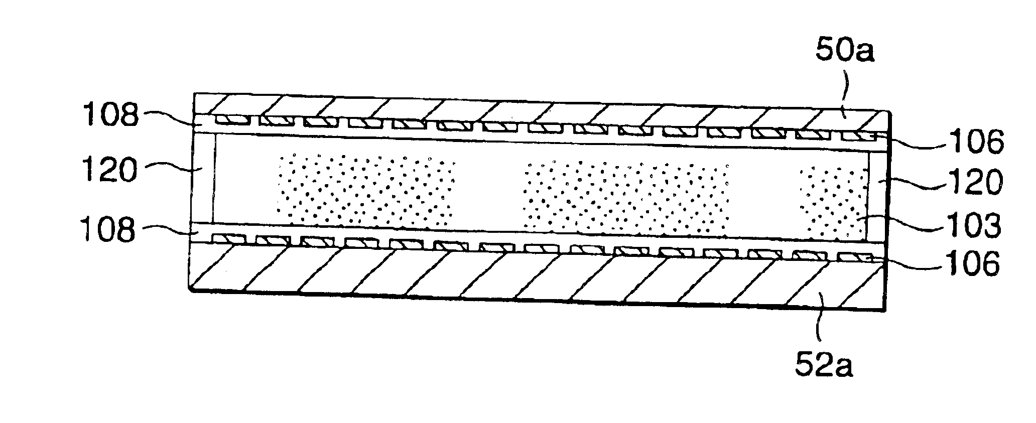
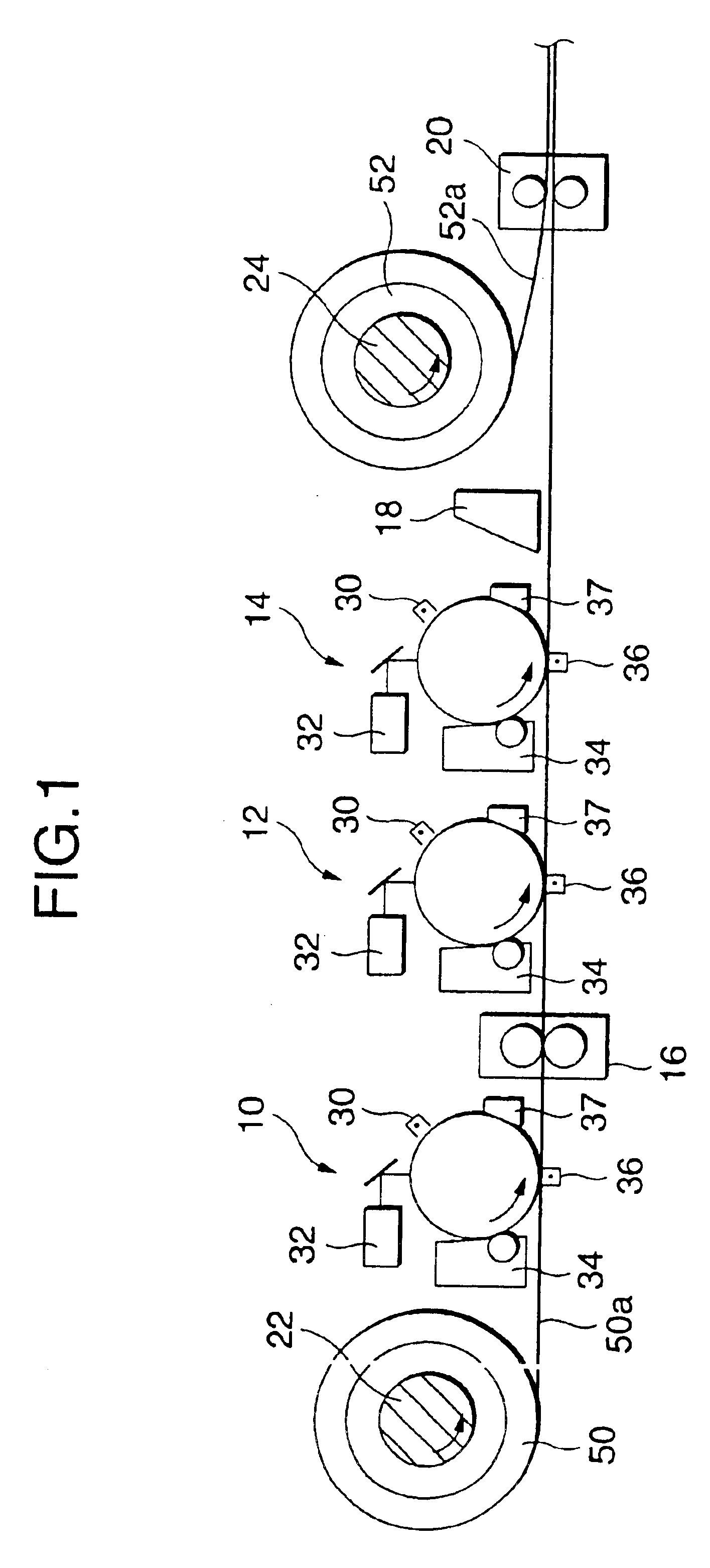
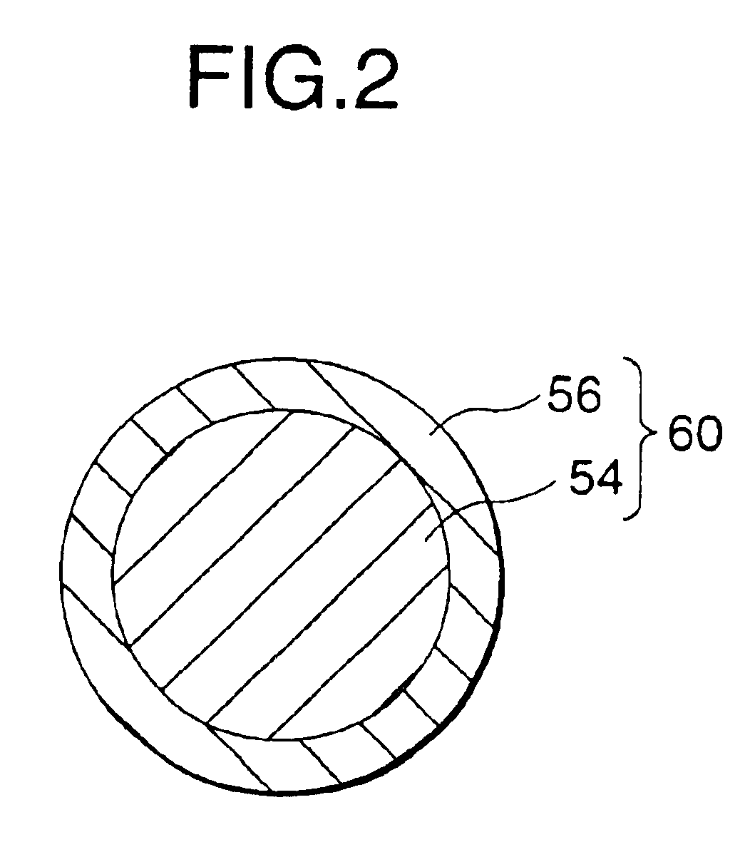
In the first embodiment of the invention, as shown in FIG. 1, by using a manufacturing line having, as roughly classified, a first electrostatic coating device 10, a second electrostatic coating device 12, a third electrostatic coating device 14, a first fixing device 16, a blade 18, a second fixing device 20, a first roller shaft 22 and a second roller shaft 24, spacer particles 60 and the particles of two colors are electrostatically coated on a first flat substrate 50a by an electrophotographic method, and a second flat substrate 52a is adhered thereto.

A first film roller 50 and a second film roller 52 are formed, for example, with PET (polyethylene terephthalate) and each is a flat substrate having a thickness of 50 μm wound into a roll form. The first film roller 50 is set on the first roller shaft 22, and the second film roller 52 is set on the second roller shaft 24, from which ends of the substrates are withdrawn and the substrates are supplied.

Between the ...

second embodiment

(Second Embodiment)

The second embodiment is a modified example of the first embodiment. As shown in FIG. 5, between a first roller shaft 22 and a second roller shaft 24, a first electrostatic coating device 10, a first fixing device 16, a second electrostatic coating device 12 and a blade 18 are arranged from the side of the first roller shaft 22. After a spacer is formed on a first flat substrate 50a supplied from a first film roller 50 by the first electrostatic coating device 10 and the first fixing device 16, black particles 62 are attached on the entire surface by the second conductive coating device 12, and the black particles 62 attached on the upper surface of the spacer particles 60 is removed by the blade 18, followed by further transporting.

On the other hand a third electrostatic coating device 14 is provided on the side of a second flat substrate 52a supplied from a second film roller 52, white particles 64 are attached on the second flat substrate 52a by the third elect...

third embodiment

(Third Embodiment)

The third embodiment is a modified example of the first embodiment. As shown in FIG. 6, on an intermediate transfer material 26 in a endless belt form rotating on a pair of rotating rollers 28, a first electrostatic coating device 10, a second electrostatic coating device 12 and the third electrostatic coating device 14 are arranged in this order. Spacer particles 60, black particles 62 and white particles 64 are transferred to the intermediate transfer material, and the spacer particles 60, the black particles 62 and the white particles 64 are transferred at a tine from the intermediate transfer material to a first flat substrate 50a by a corotron 39. Thereafter, the first flat substrate 50a is superimposed on a second flat substrate 52a, and a thermoplastic resin layer 56 on the surface of the space particles 60 between the first flat substrate 50a and the second flat substrate 52a is fused to fix the first flat substrate 50a and the second flat substrate 52a thr...


PUM


Abstract

A method for manufacturing an image displaying medium is provided in that a display element in the form of powder can be filled between facing substrates. After patterning spacer particles on a first flat substrate supplied from a first film roller set on a first roller shaft by a first electrostatic coating device, they are fixed by a first fixing device to form a spacer on the first flat substrate, and then black particles are coated, on the entire surface by a second electrostatic coating device. After coating white particles thereon by a third electrostatic coating device, the black particles and the white particles on the upper part of the spacer are removed by a blade, and a second flat substrate supplied from a second film roller set on a second roller shaft is superimposed, followed by fixing the upper part of the spacer and the second flat substrate by a second fixing device.

Description

BACKGROUND OF THE INVENTION1. Field of the InventionThe present invention relates to a method for manufacturing an image displaying medium, and in particular, it relates to a method for manufacturing an image displaying medium that can display an image repeatedly.2. Discussion of the Related ArtElectronic paper technique has been known in that a desired image is displayed on a display substrate by utilizing an electronic action. The electronic paper technique includes, as roughly classified, two constitutions, one of which has such a structure that a liquid display element or a displaying liquid of a display element dispersed in a liquid is filled between substrates that face each other, such as those utilizing electrophoresis, thermal rewritable, liquid crystal and electrochromy, and the other of which has such a structure that a display element having a powder form is filled between substrates that face each other, such as a structure shown in, FIG. 20, in which a conductive color...

Claims


Application Information

Patent Timeline
IPC IPC(8): G03G17/00G03G17/04G03G17/06G02F1/1339G09F9/37
CPCG03G17/06G03G17/04
Inventor SAKAMAKI, MOTOHIKOSHIGEHIRO, KIYOSHIYAMAGUCHI, YOSHIROOBA, SHOTANAKAYAMA, NOBUYUKIMACHIDA, YOSHINORIKOSHIMIZU, MINORUKAKINUMA, TAKEO
Owner E INK CORPORATION
Why Eureka
Try Eureka